
Auxiliary mechanism for automatically adjusting gap between vibration tables for clay sand horizontal molding machine

An automatic adjustment and auxiliary mechanism technology, applied in the direction of molding machines, molding tables, casting and molding equipment, etc., can solve the problems of increased labor intensity of the operator, weak vibration, and difficulty in the operator's proficiency, so as to improve the vibration effect, Improving production efficiency and avoiding the separation between the shock table and the piston

Pending Publication Date: 2021-03-19
厦门幻栢机械有限公司
View PDF0 Cites 1 Cited by
  • Summary
  • Abstract
  • Description
  • Claims
  • Application Information

AI Technical Summary

Problems solved by technology

[0003] Existing sand casting uses the sand box to form the upper and lower molds through the action of the core shooter, and then closes them for casting. On the one hand, this increases the labor intensity of the operator, and on the other hand, it also makes the sand casting process complicated and difficult. Operators are proficient, and the existing sand casting equipment has a complex structure and is not easy to operate, and due to long-term vibration, it is easy to cause loosening at the interface, so that there is a gap between the shock table and the piston, so the working airflow leaks from here, causing The vibration is weak, especially after compaction, and the traditional equipment has complex structure, high energy consumption and high limitation of use

Method used


Image

  • Auxiliary mechanism for automatically adjusting gap between vibration tables for clay sand horizontal molding machine
  • Auxiliary mechanism for automatically adjusting gap between vibration tables for clay sand horizontal molding machine
  • Auxiliary mechanism for automatically adjusting gap between vibration tables for clay sand horizontal molding machine

Examples


Embodiment Construction

[0023] The present invention will be further described below in conjunction with accompanying drawing:

[0024] as attached figure 1 to attach Figure 5 Shown:

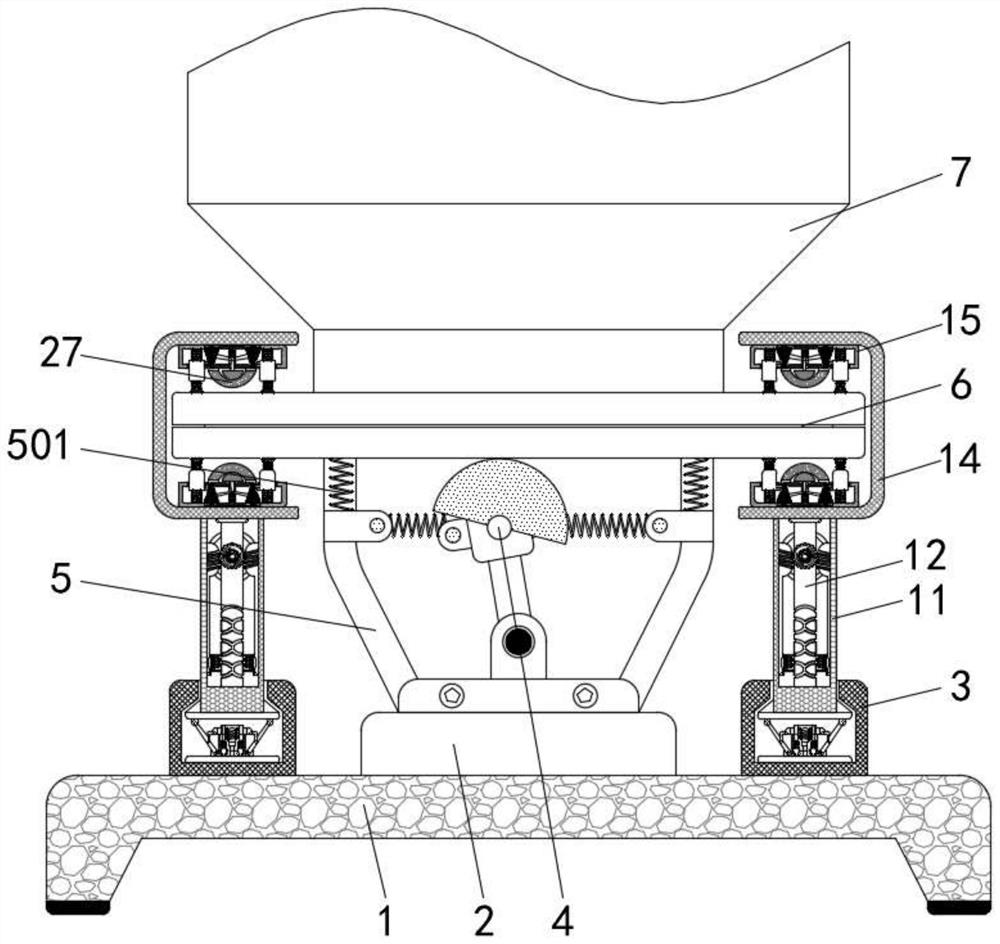
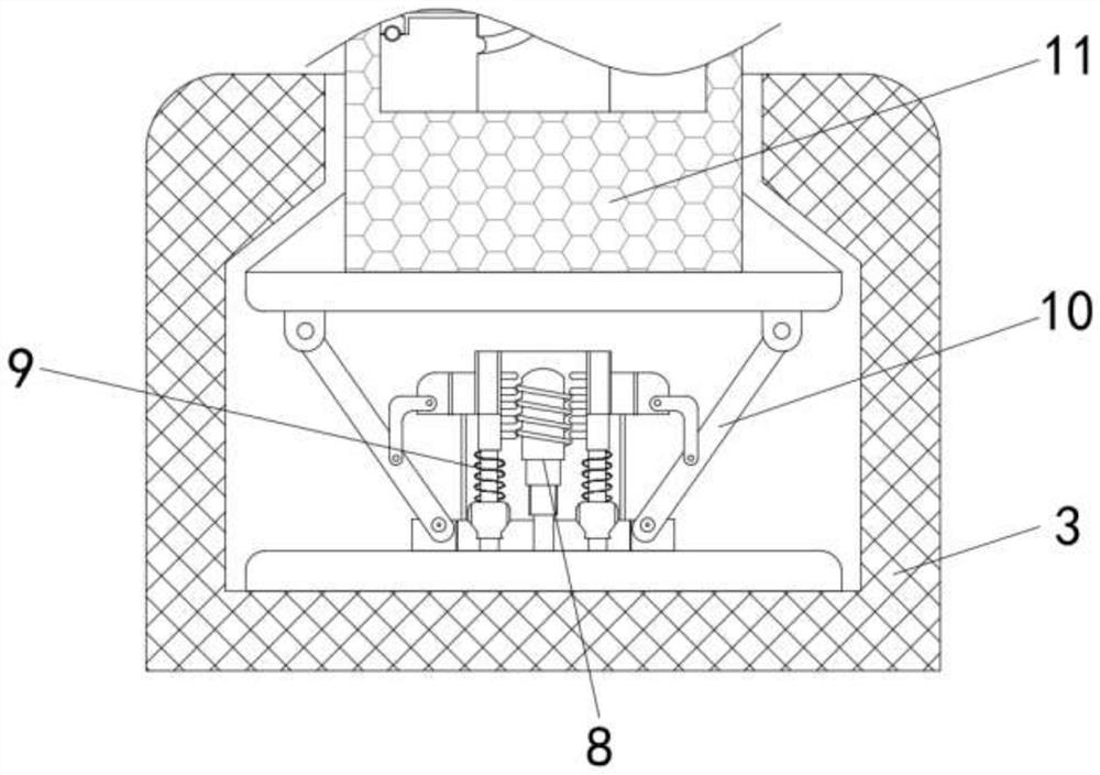
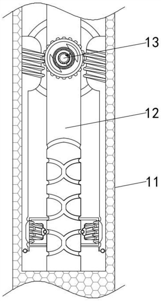
[0025] The invention provides an auxiliary mechanism for automatically adjusting the gap between shock tables for a clay sand horizontal molding machine. There are vibrating mechanism 4 and vibrating support 5, the upper side of vibrating mechanism 4 is provided with installing shock table 6, and vibrating spring 501 is installed between vibrating mechanism 4 and vibrating support 5, and the upper end of vibrating spring 501 is installed with vibrating platform 6 phase Connection, using the vibration spring 501 on the vibration bracket 5 to move synchronously, and then keep shaking, thereby effectively improving the vibration effect of the equipment shell 7, installing the vibration platform 6 to form the connection between the vibration platform and the piston, through the continuous operation of the equipment, Du...


PUM


Abstract

The invention provides an auxiliary mechanism for automatically adjusting a gap between vibration tables for a clay sand horizontal molding machine. The auxiliary mechanism comprises a base, wherein amounting base and fixing parts are fixedly mounted on the upper side of the base, a vibration mechanism and vibration supports are mounted on the upper side of the mounting base, the mounting vibration table is mounted on the upper side of the vibration mechanism, and an equipment shell is fixedly mounted on the upper side of the mounting vibration table. According to the auxiliary mechanism forautomatically adjusting the gap between the vibration tables for the clay sand horizontal molding machine, the mounting vibration table makes contact with connecting pieces so as to drive movable blocks to move downwards; mounting blocks make contact with movable mechanisms in an attached mode, so that movable connecting rods are used for pushing ejector rods to drive ejector pieces to push adjusting mechanisms to move upwards, and the adjusting mechanisms make contact with the mounting vibration table, so that the mounting vibration table is effectively and quickly reset, the vibration tableson the mounting vibration table are prevented from being separated from pistons, the vibration effect of the equipment is further improved, and the production efficiency is improved.

Description

technical field [0001] The invention belongs to the technical field of molding machines, and in particular relates to an auxiliary mechanism for automatically adjusting the gap between shaking tables for a clay-sand horizontal molding machine. Background technique [0002] The molding machine is a common casting equipment used to make sand molds. Its main function is to fill the sand, fill the loose sand into the sand box, and compact the sand. Through vibration, compaction, shock pressure, injection pressure, etc. Different methods make the loose molding sand in the sand box compact, so that the sand mold has the necessary strength during the process of handling and pouring. According to different methods, it can be divided into compaction type, vibration type, shock pressure type, injection pressure type molding machine and sand blasting machine. [0003] Existing sand casting uses the sand box to form the upper and lower molds through the action of the core shooter, and ...

Claims


Application Information

Patent Timeline
IPC IPC(8): B22C19/02B22C15/28
CPCB22C15/28B22C19/02
Inventor 林其涛
Owner 厦门幻栢机械有限公司
Learn More