
Automatic rack drilling equipment

A drilling equipment and rack technology, which is applied in drilling/drilling equipment, boring/drilling, metal processing equipment, etc., can solve problems such as low drilling efficiency, save manpower, improve drilling quality, The effect of improving efficiency

Pending Publication Date: 2021-03-19
济南鞍顺齿条有限公司
View PDF0 Cites 0 Cited by
  • Summary
  • Abstract
  • Description
  • Claims
  • Application Information

AI Technical Summary

Problems solved by technology

[0003] In view of the related technologies mentioned above, the inventor believes that there are the following defects: when drilling the rack, the worker first manually transports the rack to the rack drilling equipment, and then the rack drilling equipment drills the rack. Hole processing, and then the workers will remove the drilled rack, the drilling efficiency is low

Method used


Image

  • Automatic rack drilling equipment
  • Automatic rack drilling equipment
  • Automatic rack drilling equipment

Examples


Embodiment Construction

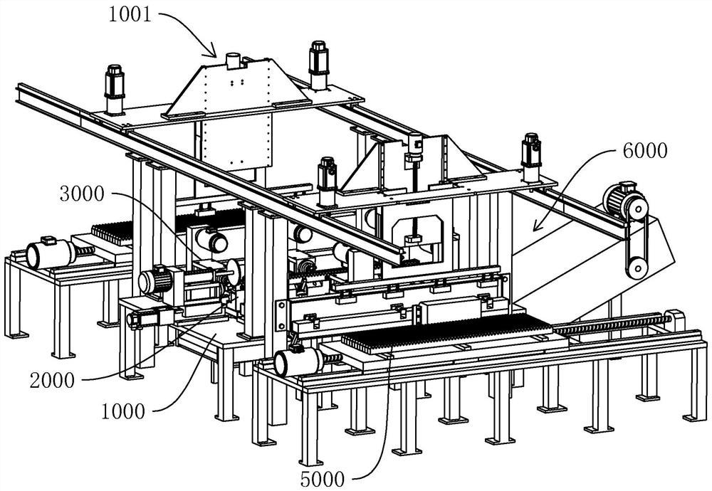
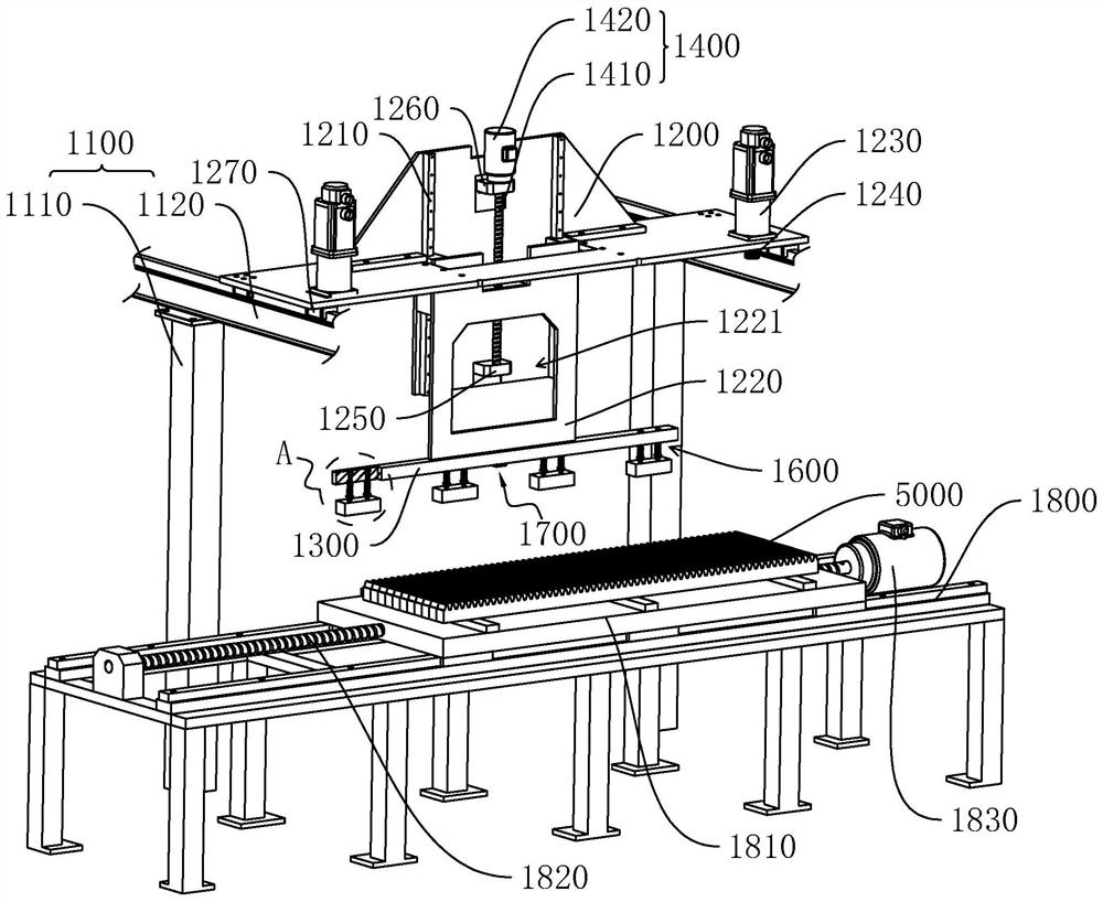
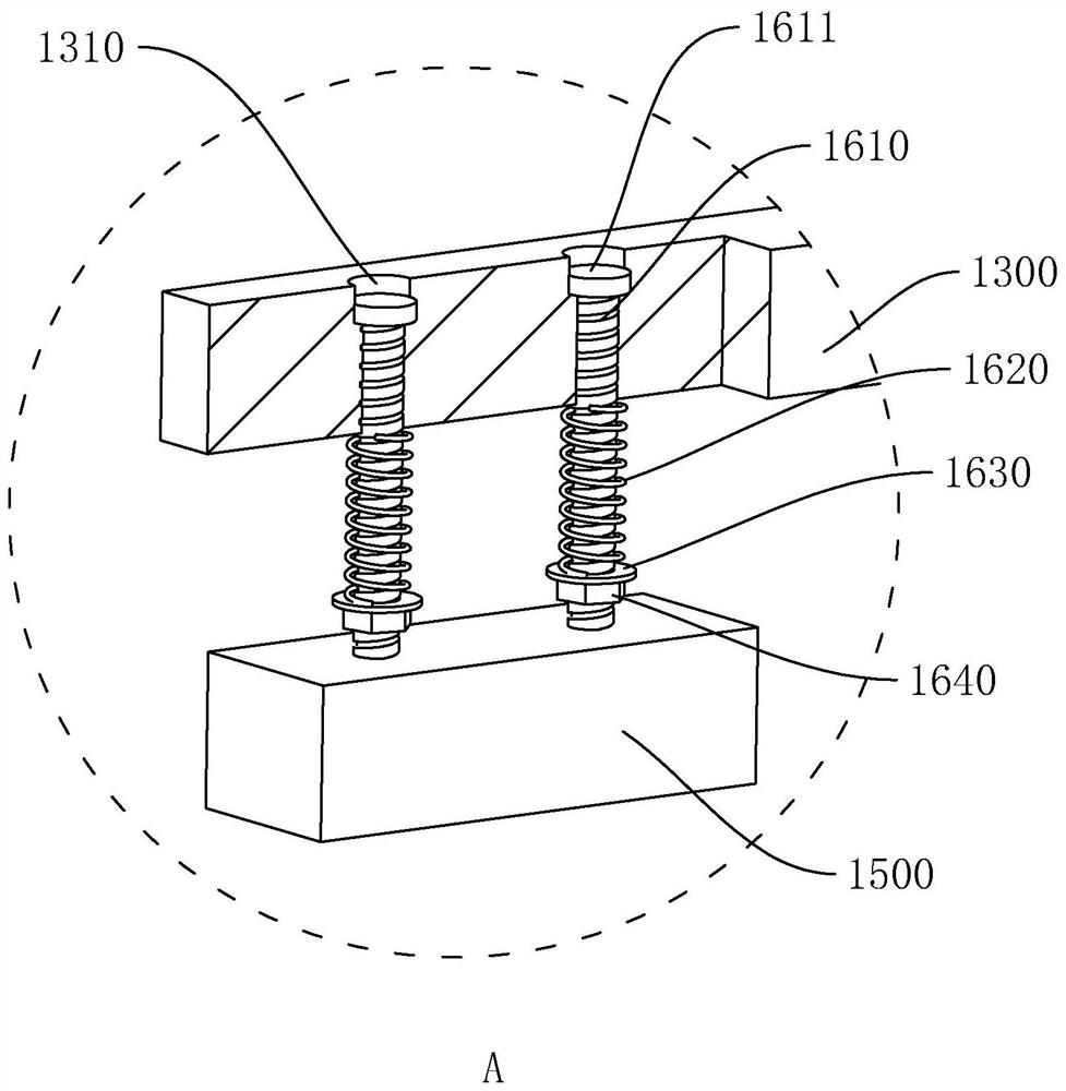
[0051] The following is attached Figure 1-9 The application is described in further detail.

[0052] The embodiment of the present application discloses a rack automatic drilling device. refer to figure 1 , including workbench 1000, workbench 1000 is provided with tooling 2000 for clamping rack 5000, and drill bit 3000 is arranged on the side of tooling 2000, and the position of drill bit 3000 corresponds to the drilling position of rack 5000. Both sides of the workbench 1000 are provided with automatic loading and unloading devices 1001 . The workbench 1000 is provided with a water outlet device on one side of the tooling 2000, and the water outlet of the water outlet device faces the tooling 2000 or the rack 5000, and the workbench 1000 is provided with a communication hole. A chip removal device 6000 is provided below the workbench 1000, and the chip removal device 6000 is located directly below the communication hole.

[0053] Utilize the automatic loading and unloadi...


PUM


Abstract

The invention relates to rack automatic drilling equipment which comprises a workbench. A tool used for clamping a rack is arranged on the workbench, drill bits are arranged on the peripheral side ofthe tool, and the positions of the drill bits correspond to the drilling positions of the rack. Automatic feeding and discharging devices are arranged on the two sides of the workbench, a water outletdevice is arranged on the workbench and located on one side of the tool, outlet water of the water outlet device faces the tool or the rack, and a communicating hole is formed in the workbench. A chip removal device is arranged below the workbench and located under the communicating hole. In the drilling process of the rack, full automation of feeding, drilling and discharging is achieved, and the drilling efficiency of the rack is improved.

Description

technical field [0001] The present application relates to the field of rack processing equipment, in particular to an automatic drilling equipment for racks. Background technique [0002] A rack is a special gear with teeth distributed on a bar-shaped body. Racks are also divided into straight toothed racks and helical toothed racks, which are paired with straight toothed cylindrical gears and helical toothed cylindrical gears respectively. When processing a rack, it is generally necessary to drill holes on both ends and / or both sides of the rack as connection holes for connecting with other equipment. [0003] In view of the related technologies mentioned above, the inventor believes that there are the following defects: when drilling the rack, the worker first manually transports the rack to the rack drilling equipment, and then the rack drilling equipment drills the rack. Holes are machined, and then the racks that have been drilled are removed by workers, so the drilli...

Claims


Application Information

Patent Timeline
Patent Type & Authority Applications(China)
IPC IPC(8): B23B39/16B23B41/00B23Q3/154B23Q11/00B23Q11/10
CPCB23B39/16B23B41/00B23Q11/00B23Q11/0042B23Q11/10B23Q3/1543
Inventor 于汉涛于广水蒋守先
Owner 济南鞍顺齿条有限公司
Learn More