
Steel pipe discharging auxiliary device and steel pipe laser drilling cutting machine

An auxiliary device and material cutting technology, which is applied in the direction of auxiliary devices, laser welding equipment, auxiliary welding equipment, etc., can solve the problems such as the inconvenience of pipe materials, and achieve the effect of improving processing accuracy and facilitating material retrieving

Active Publication Date: 2021-03-19
金成技术股份有限公司
View PDF8 Cites 4 Cited by
  • Summary
  • Abstract
  • Description
  • Claims
  • Application Information

AI Technical Summary

Problems solved by technology

[0005] In order to solve the above problems and overcome the deficiencies of the prior art, the present invention intends to provide a steel pipe unloading auxiliary device and an auxiliary device for unloading steel pipes that solve the problem of inconvenient handling of processed pipes by industrial robots due to space problems by means of clamping and dragging. Steel pipe laser drilling and cutting machine

Method used


Image

  • Steel pipe discharging auxiliary device and steel pipe laser drilling cutting machine
  • Steel pipe discharging auxiliary device and steel pipe laser drilling cutting machine
  • Steel pipe discharging auxiliary device and steel pipe laser drilling cutting machine

Examples


Embodiment 1

[0035] As mentioned above, the steel pipe laser drilling and cutting machine works on the following principles:

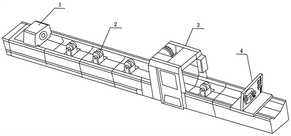
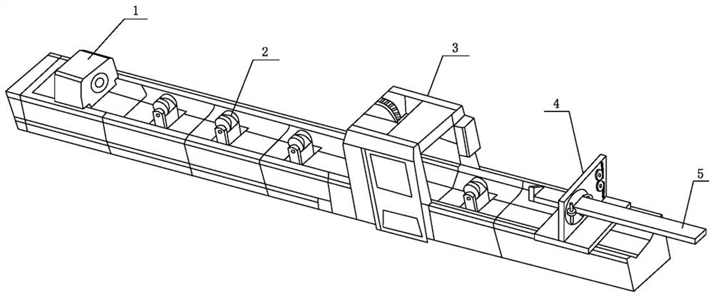
[0036] The clamping chuck clamps the pipe and pushes it forward. The pipe slides forward along the support wheel 2 and passes through the centering chuck. At the same time, the steel pipe unloading auxiliary device 4 slides to the preset position under the action of external force. When passing through the centering chuck and then entering between the two clamp arms 411, move the clamp arm 411 by hand to make the gap between the two clamp arms 411 larger. After the pipe material enters between the two clamp arms 411, loosen the grip The clamp arm 411 can clamp the pipe material.

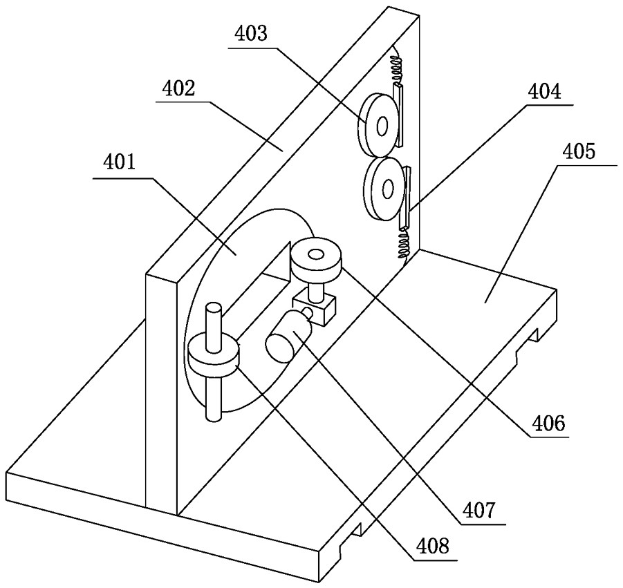
[0037]The two clamping gears 403 mesh with each other. When the clamping arms 411 are moved, no matter whether one of the clamping arms 411 is moved or both clamping arms 411 are moved at the same time, the opening range of the two clamping arms 411 is the same.

[0038] In the initial s...

Embodiment 2

[0043] Such as Figure 7 As shown, in the steel pipe laser drilling and cutting machine mentioned above, the vertical plate 402 is also provided with an electric push rod 412 that expands and contracts under external control, and the upper end of the extension part of the electric push rod 412 is connected with a plectrum , The reset rack 404 is provided with a protrusion that cooperates with the plectrum, and the initial state of the plectrum is out of contact with the protrusion of the reset rack 404 .

[0044] The working principle is:

[0045] The clamping chuck clamps the pipe and pushes it forward. The pipe slides forward along the support wheel 2 and passes through the centering chuck. At the same time, the steel pipe unloading auxiliary device 4 slides to the preset position under the action of external force. When passing through the centering chuck and then entering between the two clamp arms 411, the extension part of the electric push rod 412 stretches out, and th...


PUM


Abstract

The invention discloses a steel pipe discharging auxiliary device and a steel pipe laser drilling cutting machine. The steel pipe discharging auxiliary device comprise a bottom plate and a vertical plate fixedly connected with the bottom plate, the vertical plate is rotatably connected with two clamping power devices through two rotating shafts, the two rotating shafts penetrate through the vertical plate, clamping arms are fixedly connected to the other side of the vertical plate, and the clamping power devices are connected with reset mechanisms keeping the clamping arms swing trend towardsthe middle of the vertical plate. The steel pipe laser drilling cutting machine comprises a machine body, a machine head, a supporting wheel and a protective cover, a steel pipe blanking assisting device is arranged on the machine body on the rear portion of the protective cover, and a sliding way on the lower portion of the bottom plate is connected with a sliding rail of the machine body in a sliding mode under the action of external force. A material clamping and then dragging mode is selected, and the problem that due to the space problem of an industrial robot, a machined finished pipe product is inconvenient to take is solved.

Description

Technical field: [0001] The invention relates to the technical field of steel pipe laser cutting, and more specifically relates to a steel pipe blanking auxiliary device and a steel pipe laser drilling and cutting machine. Background technique: [0002] Steel pipe laser drilling and cutting machine is mainly used in the automatic laser processing of pipes and profiles in the automotive industry, pipe decoration, stairs, glass curtain walls, sports equipment, etc. The mass production of length is faster and more accurate than traditional processing methods. [0003] At present, the steel pipe laser drilling and cutting machine mainly includes several parts such as the feeding part, the clamping part, the laser processing part, and the blanking part. The cutting part is basically divided into two methods: manual pick-up and industrial robot pick-up; the traditional manual pick-up is less efficient, and may cause injury to workers if it is not careful. Now most factories are u...

Claims


Application Information

Patent Timeline
Patent Type & Authority Applications(China)
IPC IPC(8): B23K26/70B23K37/053B23K26/16B23K26/38B23K26/382B23K101/06
CPCB23K26/702B23K37/0533B23K26/16B23K26/38B23K26/382B23K2101/06
Inventor 姬蕾郑代顺杨绍华
Owner 金成技术股份有限公司
Learn More