
Log bark scraping machining device

A processing device and scraping technology, which is applied in the direction of wood processing equipment, bark, manufacturing tools, etc., can solve the problems of damage, cleaning, and inability to collect the log skin, and achieve the effect of improving efficiency and quality, and reducing labor intensity

Inactive Publication Date: 2021-03-19
屈龙强
View PDF7 Cites 3 Cited by
  • Summary
  • Abstract
  • Description
  • Claims
  • Application Information

AI Technical Summary

Problems solved by technology

[0005] The present invention overcomes the disadvantage that when people use the existing machinery to scrape off the log skin, the scraped log skin cannot be collected in time and cleaned quickly, and the scraped log skin may splash out and cause people to be injured. The technical problem to be solved by the present invention is to provide a log scraping processing device that is relatively safe in manual operation, and can collect the scraped skin in time and facilitate cleaning.

Method used


Image

  • Log bark scraping machining device
  • Log bark scraping machining device
  • Log bark scraping machining device

Examples


Embodiment 1

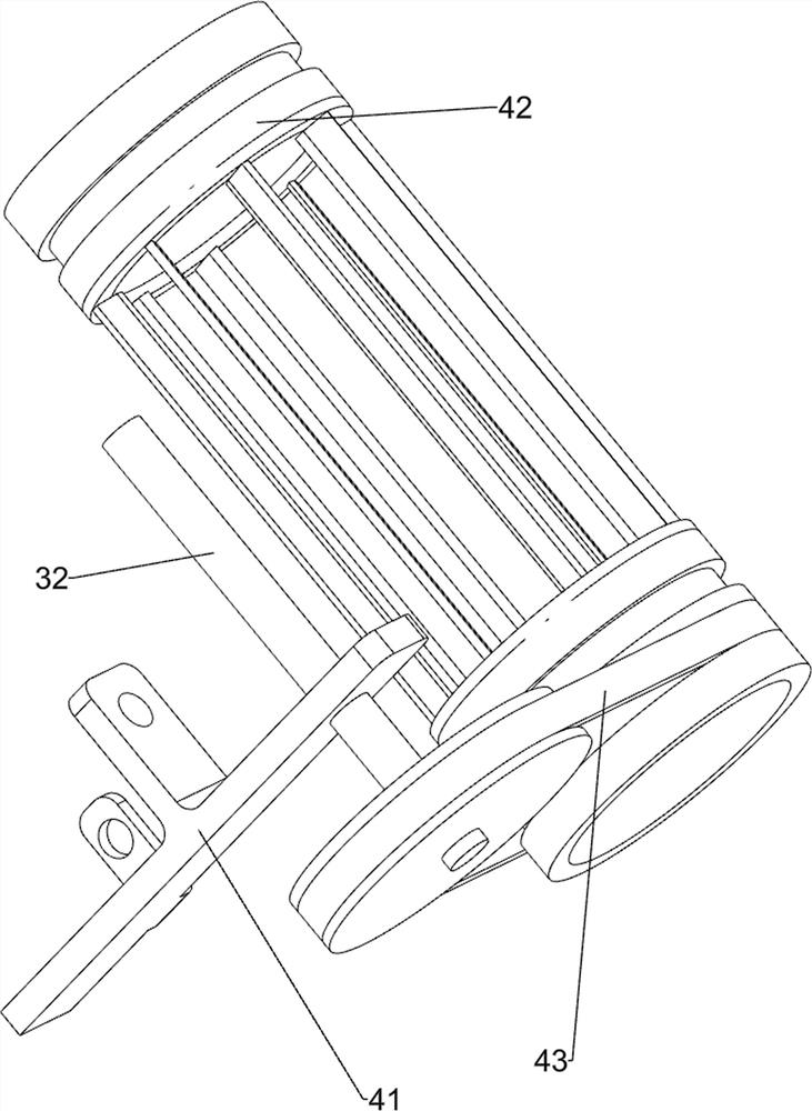
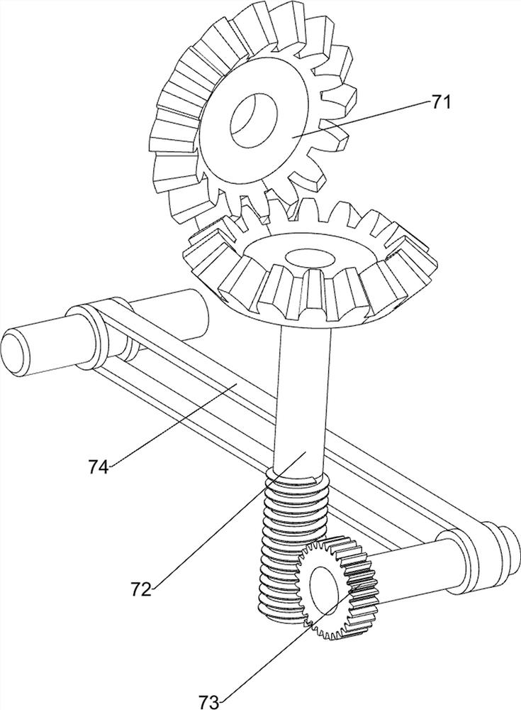
[0028] A log scraping processing device, such as Figure 1-6 As shown, it includes a base plate 1, a limit frame 2, a limit support guide frame 10, a driving mechanism 3, a cutting mechanism 4, a clamping mechanism 5, a moving mechanism 6 and a speed reduction mechanism 7. The front side of the bottom plate 1 top is connected with two A limit frame 2, the right front side of the top of the base plate 1 is connected with a limit support guide frame 10, the left front side of the top of the base plate 1 is connected with a drive mechanism 3, and a cutting mechanism 4 is connected between the top of the base plate 1 and the drive mechanism 3, and the top of the base plate 1 A moving mechanism 6 is connected in the middle, a clamping mechanism 5 is connected to the moving mechanism 6 , and a speed reduction mechanism 7 is connected between the driving mechanism 3 and the cutting mechanism 4 .

[0029] The driving mechanism 3 includes a support 30, a servo motor 31 and a rotating s...

Embodiment 2

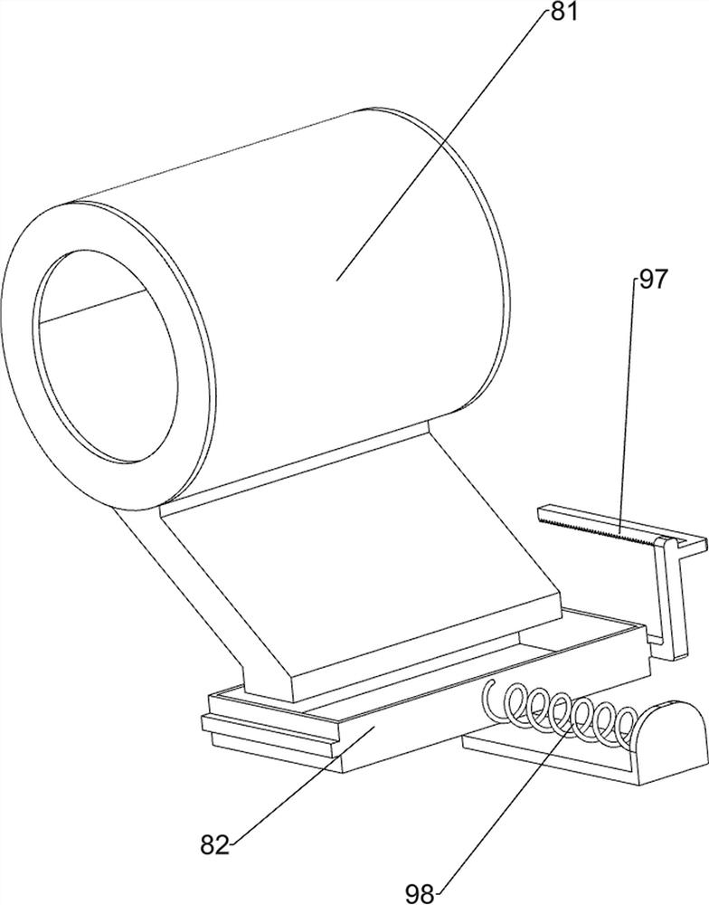
[0036] On the basis of Example 1, such as Figure 7 and Figure 8 As shown, it also includes a material receiving mechanism 8. The material receiving mechanism 8 includes a material guide hopper 81 and a material receiving box 82. The right front side of the top of the bottom plate 1 is connected with a material guide hopper 81. The material guide hopper 81 is located on the outside of the cutter frame 42. The right front side of 1 is slidably connected with receiving box 82.

[0037] Also includes opening and closing mechanism 9, and opening and closing mechanism 9 includes positioning block 91, power connecting rod 92, one-way gear 93, second bevel gear set 94, second spur gear 95, second rack rack 96, third Rack rack 97 and spring 98, the rear side of material receiving box 82 is connected with the 3rd rack rack 97, is connected with spring 98 between the right side of material receiving box 82 and base plate 1, and the top of slide block 61 is connected with the 2nd rack ...


PUM


Abstract

The invention relates to a bark scraping machining device, in particular to a log bark scraping machining device. The log bark scraping machining device provided by the invention is safer during manual operation, can collect scraped bark in time and is convenient to clean. The log bark scraping machining device comprises at least two limiting frames connected to a bottom plate, a limiting supporting guide frame connected to the side, close to the limiting frames, of the bottom plate, a driving mechanism connected to the side, close to the limiting supporting guide frame, of the bottom plate, acutting mechanism connected between the bottom plate and the driving mechanism, a moving mechanism connected to the side, close to the driving mechanism, of the bottom plate, and a clamping mechanismconnected to the moving mechanism. Under the action of the driving mechanism, the cutting mechanism, the clamping mechanism, the moving mechanism and a speed reducing mechanism, the bark of a log canbe quickly and uniformly scraped.

Description

technical field [0001] The invention relates to a scraping processing device, in particular to a log scraping processing device. Background technique [0002] Since trees are renewable resources, when people use trees to make various products, they need to scrape off the bark of trees. However, the current method of scraping the bark of trees is generally to scrape and cut the bark of trees back and forth by hand-held knives. Such manual operation is labor-intensive and is not suitable for operating large quantities of trees. Therefore, it is necessary to design a Used for log scraping processing equipment. [0003] After retrieval, the patent publication number is: the patent of CN100423917C, discloses a kind of peeling bark mechanical device (1), is used for peeling off log outer bark or carries out pretreatment to the log of last separate peeling, and is used for discharging from passing through peeling tree At least some bark stripped from the stream of logs of a barki...

Claims


Application Information

Patent Timeline
Patent Type & Authority Applications(China)
IPC IPC(8): B27L1/10B27G3/00
CPCB27G3/00B27L1/10
Inventor 屈龙强
Owner 屈龙强
Learn More