Sludge treatment system

A sludge treatment and sludge technology, applied in the field of sludge treatment system, can solve the problems of unconsidered equal-diameter structure, inability to realize manual takeover, damage to the filter screen, etc., so as to improve the space utilization rate and avoid the effect of manpower being unable to drive.

Pending Publication Date: 2021-03-19
CHANGSHA UNIVERSITY OF SCIENCE AND TECHNOLOGY
View PDF8 Cites 2 Cited by
  • Summary
  • Abstract
  • Description
  • Claims
  • Application Information

AI Technical Summary

Problems solved by technology

[0005] 1. The dredging equipment in the prior art separates sewage through the filter screen, but the silt falling from a high place will impact the filter screen, and the impact force will cause undesired substances to pass through the filter screen, or the impact force will damage the filter screen
[0006] 2. In the prior art dredging equipment, the screw extrusion column is often of equal-diameter structure, but the equal-diameter structure does not consider many factors such as: the size of the passage space of the medium and the extrusion force of the medium, so the function is single
[0007] 3. In the dredging equipment of the prior art, the screw extrusion column is driven by a motor, but the motor often needs to be additionally equipped with a riser or a support frame, which increases the volume and increases the cost
[0008] 4. The dredging equipment in the prior art is often discharged directly after the sludge is squeezed, and lacks the on-off control and adjustment of the sludge discharge. In some special working conditions such as when the downstream storage room is full, it cannot be switched on and off in time. Manual intervention, watching downstream storage chambers to prevent overfilling
[0009] 5. The dredging equipment in the prior art has cleaning needs, and an additional independent cleaning channel will be provided. However, if additional functions such as valve functions and manual drive functions are added, the superposition of too many functions will lead to increased costs and increased volume. Big
[0010] 6. In the dredging equipment of the prior art, the screw extrusion column is driven by a motor, which cannot be manually taken over in an emergency. There may be a technology that is driven by a motor or a manual drive device at the same time, but this drive does not consider the manual drive device Rotation arm size

Method used


Image

  • Sludge treatment system
  • Sludge treatment system
  • Sludge treatment system

Examples


Embodiment Construction

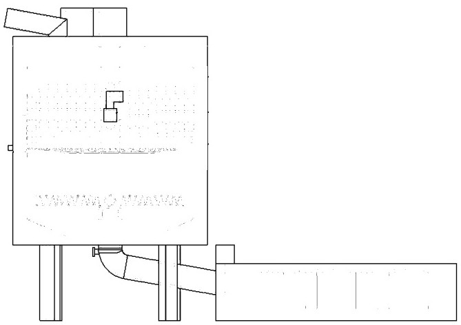
[0045] As shown in the figure: a sludge treatment system, the sludge treatment system includes a sand and gravel separation module, a liquid medicine mixing module, and a sludge dehydration module; the sludge is sequentially processed through the sand and stone separation module, the medicine liquid mixing module, and the sludge dehydration module;

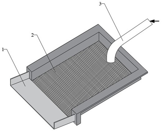
[0046] The sand and gravel separation module includes a vibrating screen, a screen and a gravel plate are arranged on the vibrating screen, and the sludge conveying pipe transports the sludge to the screen, and the mud seeps down through the gaps of the screen, and the sand that does not pass through the screen passes through the sieve. The above-mentioned gravel board enters the gravel collection bag;

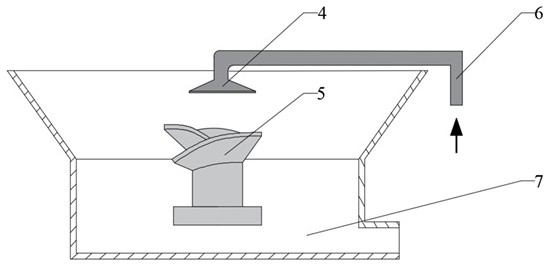
[0047] The liquid medicine mixing module includes a funnel, a liquid medicine mixing tank is arranged in the funnel, a stirring column is arranged in the liquid medicine mixing tank, a liquid medicine delivery pipe transports the m...


PUM


Abstract

The invention discloses a sludge treatment system. The sludge treatment system comprises a sand-stone separation module, a liquid medicine mixing module and a sludge dehydration module, wherein the sludge sequentially passes through the sand-stone separation module, the liquid medicine mixing module and the sludge dehydration module to be treated; the sand-stone separation module comprises a vibrating screen, a screen mesh and a sand-stone plate are arranged on the vibrating screen, a sludge conveying pipe conveys sludge to the screen mesh, slurry infiltrates downwards through a gap of the screen mesh, and sand-stone incapable of passing through the screen mesh enters a sand-stone collection bag through the sand-stone plate.

Description

technical field [0001] The invention relates to the field of urban pipeline dredging, in particular to a sludge treatment system. Background technique [0002] Silt is a common sediment in urban pipelines, mainly distributed in urban road sewers, reservoirs, sewage pipes, etc., containing a large amount of impurities such as clay, sand, and organic sediments. Silt is easy to adhere to the inner wall of the pipeline, forming a silt layer, which hinders the sewer pipeline The water body flows, and the organic substances contained in it may ferment and deteriorate under the action of the environment, breed bacteria, and pollute the environment. With the development of cities in our country, the dredging of underground waterways is becoming more and more important. The rapid and efficient treatment of the silt cleaned from the pipeline is of great significance to the construction of the urban environment. The method of directly sucking out the sludge with a pump suction truck i...

Claims


Application Information

Patent Timeline
Patent Type & Authority Applications(China)
IPC IPC(8): C02F11/125C02F11/00
CPCC02F11/125C02F11/00
Inventor 舒之睿毛聪
Owner CHANGSHA UNIVERSITY OF SCIENCE AND TECHNOLOGY
Why Eureka
Try Eureka