Lubricating oil system of gas turbine

A technology of gas turbine and lubricating oil, which is applied in the direction of gas turbine device, engine lubrication, turbine/propulsion device lubrication, etc., and can solve problems such as increasing oil consumption, hindering system oil return, and polluting the environment

Pending Publication Date: 2021-03-19
上海和兰透平动力技术有限公司
View PDF0 Cites 0 Cited by
  • Summary
  • Abstract
  • Description
  • Claims
  • Application Information

AI Technical Summary

Problems solved by technology

[0005] The existing gas turbine lubricating oil system is mostly designed independently of the gas turbine soundproof box, and is located outside the soundproof box, which leads to poor integrity of the gas turbine and is not conducive to the transportation of the unit, especially for the mobile unit used as an emergency power supply. It is even more inconvenient
During the operation of the unit, the lubricating oil in the oil tank is heated and evaporated to produce oil mist, which is also mixed with carbonized fine particles; the generation of oil mist creates a slight positive pressure in the oil tank, which hinders the oil return of the system; the existing gas turbine lubricating oil system is Most of the oil mist is treated by direct discharge or discharge after simple filtration, which seriously pollutes the environment, increases oil consumption, greatly increases the concentration of PM2.5 particles inside the plant, and hinders the health of operators

Method used


Image

  • Lubricating oil system of gas turbine

Examples


Embodiment 1

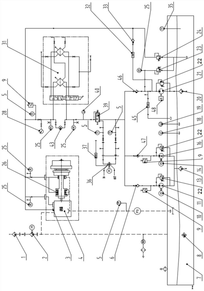
[0091] Such as figure 1 As shown, the gas turbine lubricating oil system includes a main pump 21, an auxiliary pump 16, an oil combination valve block, an oil separation valve block, and a main pump pre-lubrication pipeline;

[0092] The main pump 21 pumps out lubricating oil from the lubricating oil tank 7 during its work and sends it to the main oil supply pipeline through the main pump pipeline through the oil valve block;

[0093] The auxiliary pump 16 pumps out lubricating oil from the lubricating oil tank 7 during its work and sends it to the main oil supply pipeline through the auxiliary pump pipeline through the oil valve block;

[0094] The main pump pipeline is provided with a main pump check valve 46, and the liquid inlet of the main pump check valve 46 is on the side of the main pump 21;

[0095] The auxiliary pump pipeline is provided with an auxiliary pump check valve 47, and the liquid inlet of the auxiliary pump check valve 47 is on the side of the auxiliary p...

Embodiment 2

[0105] Based on Embodiment 1, the gas turbine lubricating oil system also includes a backup pump 11;

[0106] The standby pump 11 pumps lubricating oil from the lubricating oil tank 7 and sends it to the main oil supply pipeline through the standby pump pipeline through the oil valve block when it works;

[0107] A backup pump check valve 6 is arranged on the backup pump pipeline, and the liquid inlet of the backup pump check valve 6 is on the side of the backup pump 11 .

[0108] In the gas turbine lubricating oil system of Embodiment 2, three pumps, the main pump 21 , the auxiliary pump 16 and the standby pump 11 , provide lubricating oil for the main oil supply pipeline. The check valve makes the oil passages of the main pump 21, auxiliary pump 16 and backup pump 11 independent without interfering with each other. During the operation of the gas turbine, through the mutual cooperation of the three pumps, the gas turbine bearing chamber 26, the gearbox 4 and the output shaft...

Embodiment 3

[0110] Based on the second embodiment, the gas turbine lubricating oil system also includes a control circuit;

[0111] The auxiliary pump 16 is driven by an AC motor 14, and the AC motor is powered by a diesel generator before the gas turbine is started, and is switched to a gas turbine for power supply after the gas turbine is started;

[0112] The standby pump 11 is driven by a DC motor 10, and the DC motor is powered by a battery pack;

[0113] The control circuit:

[0114] When the gas turbine stops for more than the set time (for example, 30 minutes), before the gas turbine is started, the standby pump 11 is controlled not to work, and the diesel generator is controlled to start to supply power to the AC motor 14 to drive the auxiliary pump 16 to work. Pump oil from the lubricating oil tank 7, and the main pump 21 The gas turbine cannot be driven by the auxiliary gear 48 of the gearbox to work because the gas turbine is not started;

[0115] During the start-up process o...


PUM


Abstract

The invention discloses a lubricating oil system of a gas turbine. The lubricating oil system of the gas turbine is characterized in that a main pump and an auxiliary pump are used for providing lubricating oil for a main oil supply pipeline, oil discharged from an oil distribution valve block respectively enters a to-be-lubricated part of the gas turbine according to flow requirements to cool andlubricate the to-be-lubricated part, and another branch of oil is led to a main pump pre-lubrication pipeline, and enters a pump cavity of the main pump through a main pump pre-lubrication one-way valve and a main pump pre-lubrication flow limiter on the main pump pre-lubrication pipeline to pre-lubricate the main pump. According to the lubricating oil system of the gas turbine, before the gas turbine is started, the main pump does not work, the main pump can be pre-lubricated, the service life of the main pump is effectively prolonged, the main pump pre-lubrication flow limiter on the main pump pre-lubrication pipeline can effectively control the pre-lubrication flow of the main pump, and the main pump pre-lubrication one-way valve can prevent the pumping-out flow from leaking when the main pump operates.

Description

technical field [0001] The invention relates to a gas turbine, in particular to a gas turbine lubricating oil system. Background technique [0002] A gas turbine is a rotary power machine that uses continuously flowing gas as a working medium to convert heat energy into mechanical work. In the main process of air and gas, only the gas turbine cycle composed of three major components: the compressor (Compressor), the combustor (Combustor) and the gas turbine (Turbine), is generally called a simple cycle. Most gas turbines use a simple cycle scheme. Because its structure is the simplest, and it can best reflect a series of advantages of gas turbines, such as small size, light weight, quick start, and less or no cooling water. [0003] The working process of the gas turbine is that the compressor (that is, the compressor) continuously inhales air from the atmosphere, and compresses it step by step through the axial flow compressor to increase the pressure, and at the same tim...

Claims


Application Information

Patent Timeline
IPC IPC(8): F02C7/06F02C7/36F02C9/00F04B23/04F04B17/03F04B49/22F02B63/04
CPCF02B63/04F02C7/06F02C7/36F02C9/00F04B17/03F04B23/04F04B49/22
Inventor 张智伟李宝杜波
Owner 上海和兰透平动力技术有限公司
Why Eureka
Try Eureka