Eureka AIR delivers breakthrough ideas for toughest innovation challenges, trusted by R&D personnel around the world.

Radial plunger pump

A technology of radial column and plug pumps, which is applied in the direction of pumps, multi-cylinder pumps, liquid displacement machines, etc. It can solve the problems of leakage, increased flow distribution gap, large bending deformation of oil distribution shaft, etc., and reduce wear , The effect of improving the problem of bending deformation

Active Publication Date: 2021-03-19
常志
View PDF6 Cites 2 Cited by
  • Summary
  • Abstract
  • Description
  • Claims
  • Application Information

AI Technical Summary

Problems solved by technology

[0003]In the prior art, the radial piston pump with the axial flow distribution method will cause the wear of the distribution shaft due to the processing and assembly of the oil distribution shaft and the cylinder block, so that the The distribution gap is increasing, and the leakage problem is becoming more and more serious, which greatly affects the volumetric efficiency of the radial piston pump.
In particular, the oil distribution shaft is affected by the radial unbalanced hydraulic pressure, resulting in a large amount of bending deformation of the oil distribution shaft and large wear of the oil distribution shaft, which shortens the service life of the radial piston pump. The large size, complex structure and poor self-priming ability limit the improvement of the speed and pressure level of the radial piston pump.

Method used


Image

  • Radial plunger pump
  • Radial plunger pump
  • Radial plunger pump

Examples


Embodiment Construction

[0034] The present invention will be described in further detail below in conjunction with the accompanying drawings and specific embodiments.

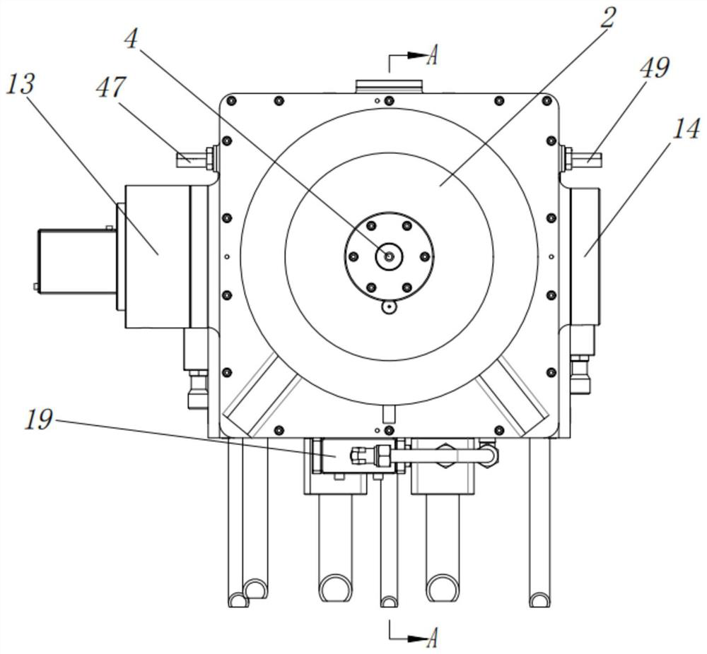
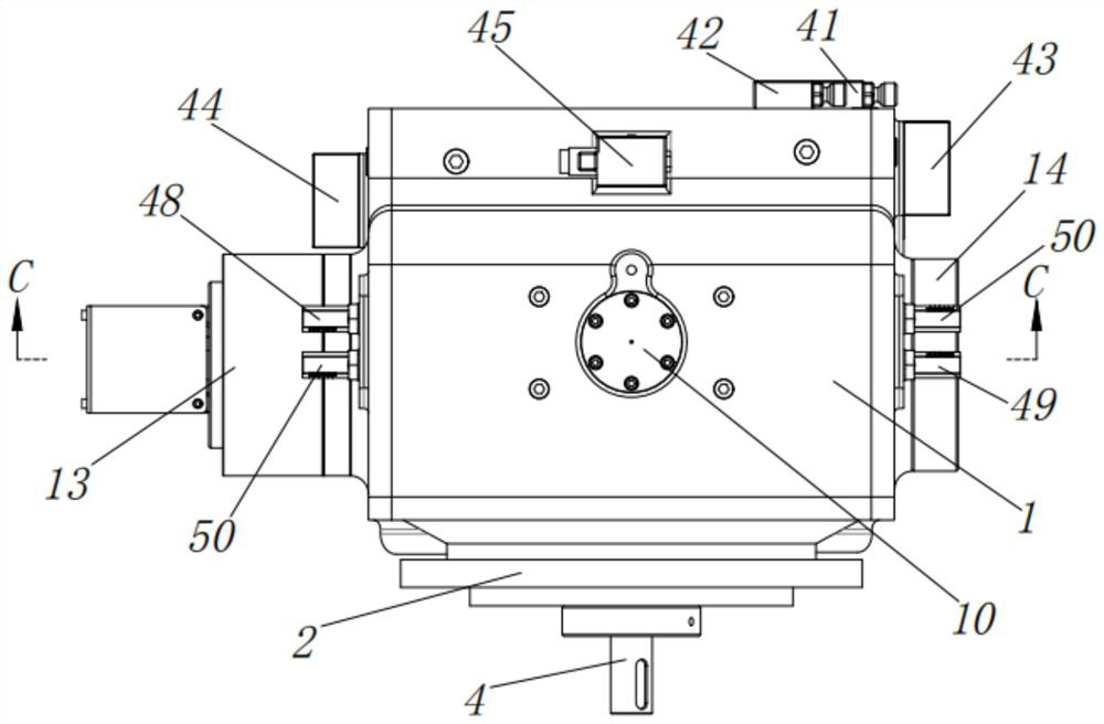
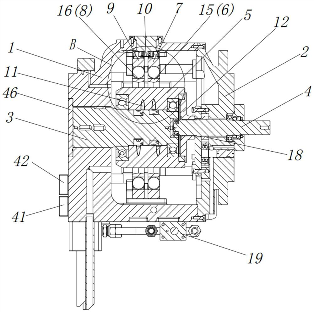
[0035] Figure 1 to Figure 17 An embodiment of the radial piston pump of the present invention is shown. The radial piston pump of this embodiment includes a housing 1, an oil distribution shaft 3, a rotor 5, and a transmission shaft 4 for driving the rotor 5 to rotate. It also includes a stator assembly 15 sleeved on the outer periphery of the rotor 5, and a sliding seat assembly 16 for adjusting the eccentricity between the stator assembly 15 and the rotor 5, the oil distribution shaft 3 is arranged in the housing 1, and the The transmission shaft 4 is arranged on the housing 1, and the oil distribution shaft 3 is provided with a first oil distribution window 31 and a second oil distribution window 32 for balancing the radial force on the oil distribution shaft 3 , the rotor 5 is provided with a plurality of plungers 11 correspondi...


PUM


Abstract

The invention discloses a radial plunger pump. The radial plunger pump comprises a shell, an oil distribution shaft, a rotor and a transmission shaft used for driving the rotor to rotate, and furthercomprises a stator assembly arranged on the periphery of the rotor in a sleeving mode and a sliding base assembly used for adjusting the eccentric distance between the stator assembly and the rotor, the oil distribution shaft is arranged in the shell, the transmission shaft is arranged on the shell, the oil distribution shaft is provided with a first oil distribution window and a second oil distribution window which are used for balancing radial acting force borne by the oil distribution shaft, and the rotor is provided with a plurality of plungers corresponding to the first oil distribution window and the second oil distribution window. Through the design of radial stress balance of the oil distribution shaft, the problem of bending deformation of the oil distribution shaft is greatly solved, abrasion between the rotor and the oil distribution shaft is reduced, and the pressure grade of the radial plunger pump is improved.

Description

technical field [0001] The invention relates to the technical field of plunger pumps, in particular to a radial plunger pump. Background technique [0002] The plunger pump realizes oil suction and oil discharge through the change of the sealed working volume when the plunger reciprocates in the plunger hole. Because the plunger and the inner hole of the cylinder are both cylindrical surfaces, and the sliding surface has high matching precision, this type of pump is characterized by small leakage, high volumetric efficiency, and can work under high pressure conditions. [0003] In the prior art, the radial piston pump with axial flow distribution method will cause the wear of the distribution shaft due to the processing and assembly of the oil distribution shaft and the cylinder body, so that the flow distribution gap will continue to increase, and the leakage problem will become more and more serious, which will have a great impact on Volumetric efficiency of radial piston...

Claims


Application Information

Patent Timeline
IPC IPC(8): F04B1/053F04B1/0404F04B1/0452
CPCF04B1/053F04B1/0404F04B1/0452
Inventor 常志
Owner 常志
Why Eureka
Eureka Blog
Learn More