Method for testing reliability of electro-hydraulic-magnetic-hybrid-loaded servo power tool rest

A dynamic tool holder and hybrid loading technology, which is used in the testing of mechanical parts, the testing of machine/structural parts, measuring devices, etc., can solve the problems of poor load simulation effect, high loading cost of power head, and only torque can be applied.

Active Publication Date: 2021-03-19
JILIN UNIV
View PDF8 Cites 2 Cited by
  • Summary
  • Abstract
  • Description
  • Claims
  • Application Information

AI Technical Summary

Problems solved by technology

[0003] The purpose of the present invention is to solve the problem that the prior art cannot carry out the reliability test on multiple power heads and common cutting heads of the multi-power head tool holder at the same time; Low load and can only apply torque, poor load simulation effect, etc., and provides a reliability test method for electro-hydraulic-magnetic hybrid loading of servo-powered tool holders;

Method used


Image

  • Method for testing reliability of electro-hydraulic-magnetic-hybrid-loaded servo power tool rest
  • Method for testing reliability of electro-hydraulic-magnetic-hybrid-loaded servo power tool rest
  • Method for testing reliability of electro-hydraulic-magnetic-hybrid-loaded servo power tool rest

Examples


Embodiment 1

[0078] Example 1 Electro-hydraulic-magnetic hybrid loaded servo power tool holder reliability test platform

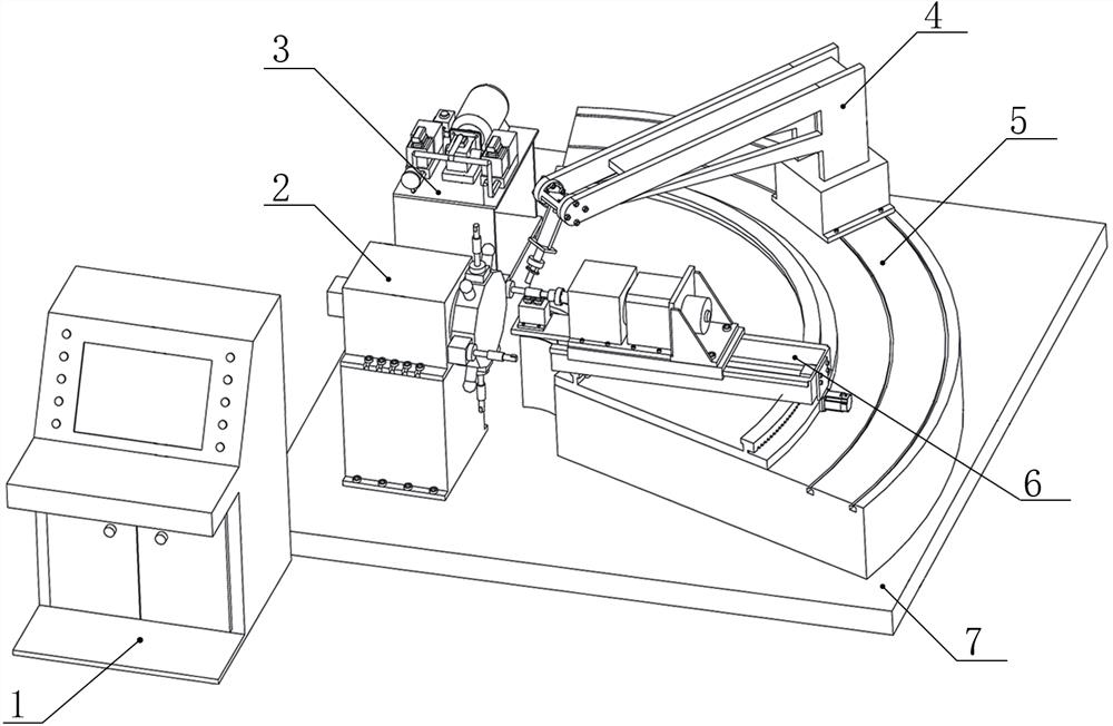
[0079] Electro-hydraulic-magnetic hybrid loading servo power tool post reliability test platform, which includes: console 1, tool post 2, hydraulic system 3, common tool head loading system 4, loading system base 5, power head loading system 6;

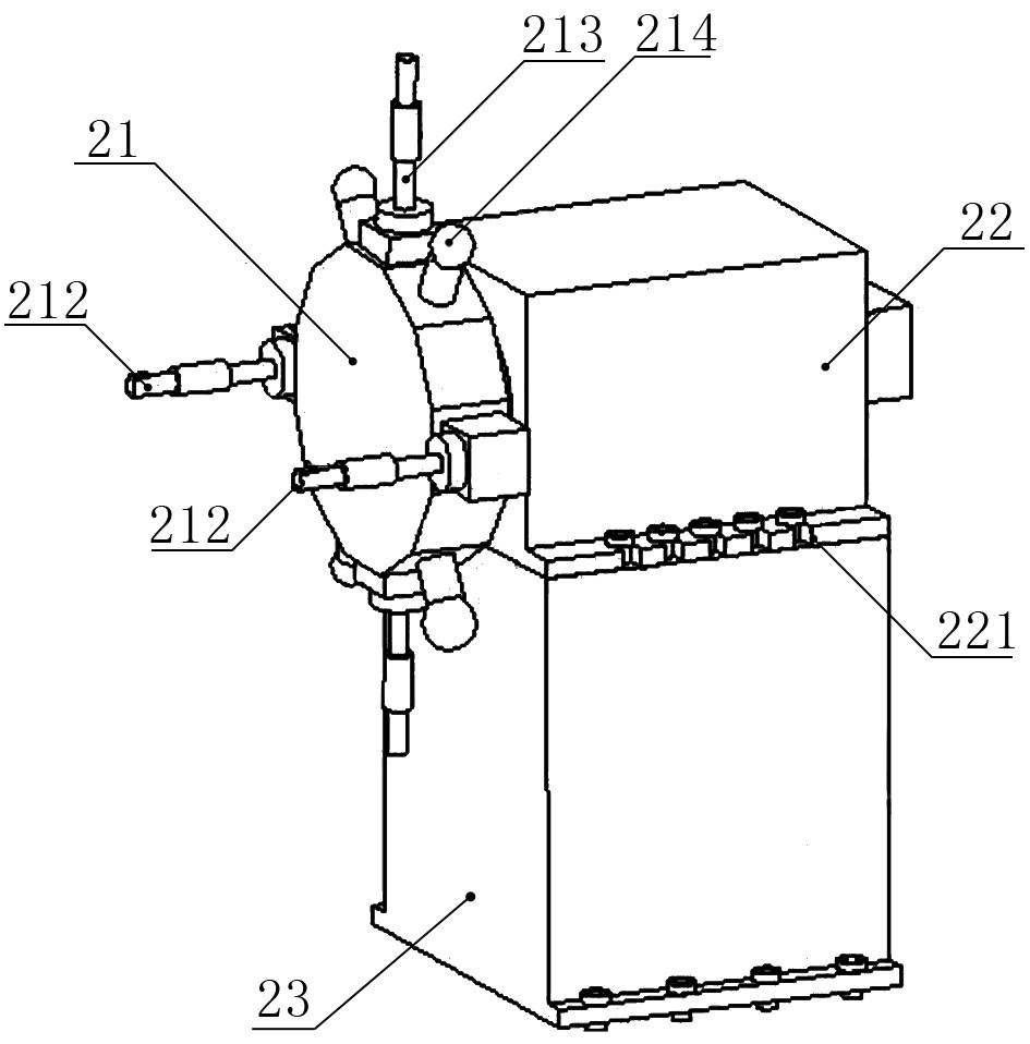
[0080] The console 1 is provided with a signal connection end, and the signal connection end is respectively connected with the tool rest 2, the hydraulic system 3, the force sensor 413 in the common cutter head loading system 4, and the electric dynamometer 65 in the power head loading system 6. , the force detection coil 612, and the displacement sensor 614 are electrically connected; the loading process of the tool holder is controlled through the console 1, and the load loading is detected;

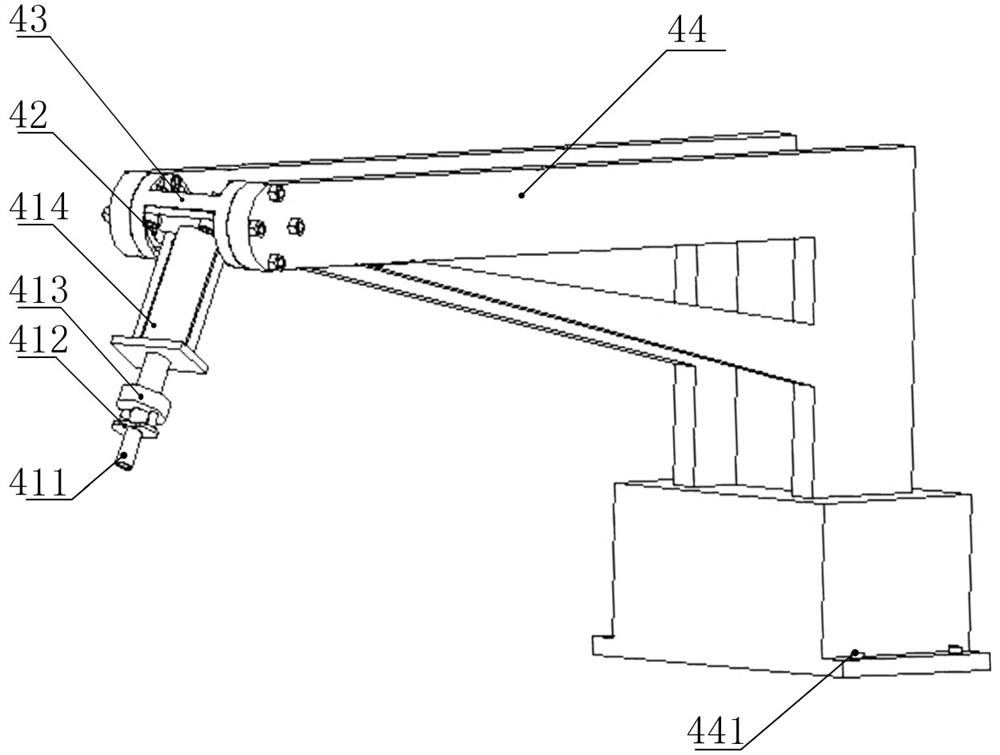
[0081] The common cutter head loading system 4 and the power head loading system 6 are installed on the loading system base 5; the t...

Embodiment 2

[0118] Embodiment 2 Electro-hydraulic-magnetic hybrid loading servo power tool post reliability testing method

[0119] refer to Figure 9 , Figure 10 The reliability test method of the servo-powered tool post with electro-hydraulic-magnetic hybrid loading mainly includes the servo-powered tool post indexing test, the servo-powered tool post ordinary tool head loading test, the servo-powered tool post 90° loading test and the servo-powered tool post 180° loading test Test, method steps are as follows:

[0120] 1. Indexing test of the power servo tool post;

[0121] 1) Keep the test temperature constant at 23°C, and place the test bench in the test environment for more than 8 hours;

[0122] 2) Ensure that the ordinary cutter head loading system 4 and the power head loading system 6 are in a separated state;

[0123] 3) Make sure that the hydraulic system 3 is in normal working condition;

[0124] 4) Select servo powered tool post indexing test on console 1;

[0125] 5) ...


PUM


Abstract

The invention discloses a method for testing reliability of an electro-hydraulic-magnetic-hybrid-loaded servo power tool rest. An electro-hydraulic and magnetic hybrid loading servo power tool rest reliability test platform comprises a console, a tool rest, a hydraulic system, a common tool bit loading system, a loading system base and a power head loading system. A servo power tool rest transposition test, a servo power tool rest common tool bit loading test, a servo power tool rest 90-degree loading test and a servo power tool rest 180-degree loading test are carried out; the power head loading system can realize conversion between 90-degree power head loading and 180-degree power head loading; a dynamic load is loaded and applied and a dynamic load condition is detected; the dynamic force application condition is detected and recorded through a displacement sensor and a force detection coil, and the torque application condition is obtained through an electric dynamometer.

Description

technical field [0001] The invention belongs to the technical field of numerical control mechanical testing equipment and methods, in particular to a method for testing the reliability of a servo-powered tool holder with electro-hydraulic and magnetic hybrid loading. Background technique [0002] As the key functional component of CNC lathe, the CNC tool post's failure directly affects the machining accuracy and work efficiency of the lathe. Throughout the current reliability test benches for CNC tool holders at home and abroad, most of them are reliability test devices for ordinary cutting tool holders, a few reliability test devices with single power heads, and reliability devices for multi-power head tool holders. There are few, and it is impossible to reliably load the multi-power head and the ordinary loading head at the same time. As the market demand for multi-power head tool holders gradually increases, the reliability test device for multi-power head servo-powered ...

Claims


Application Information

Patent Timeline
Patent Type & Authority Applications(China)
IPC IPC(8): G01M13/00
CPCG01M13/00
Inventor 杨兆军刘严何佳龙张正阳钟源韩良晟孔令达王子康何禹志
Owner JILIN UNIV
Why Eureka
Try Eureka