
Open-circuit fault diagnosis method for neutral-point clamped single-phase three-level inverter
A three-level inverter, open-circuit fault technology, applied in the measurement of electrical variables, instruments, measurement of electricity and other directions, can solve the problems of affecting system reliability, large data processing volume of data processing algorithms, and difficulty in online implementation.
- Summary
- Abstract
- Description
- Claims
- Application Information
AI Technical Summary
Problems solved by technology
Method used
Image

Examples
Embodiment Construction
[0041] An embodiment of the present invention will be further described below in conjunction with accompanying drawing:
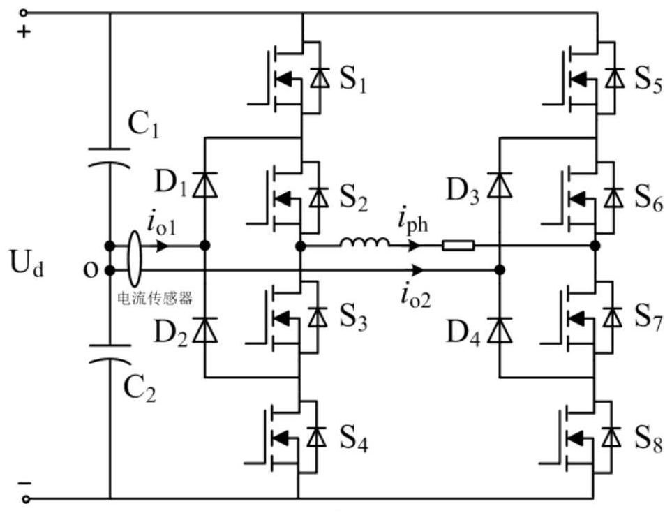
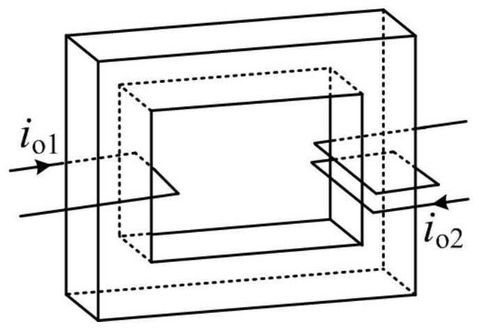
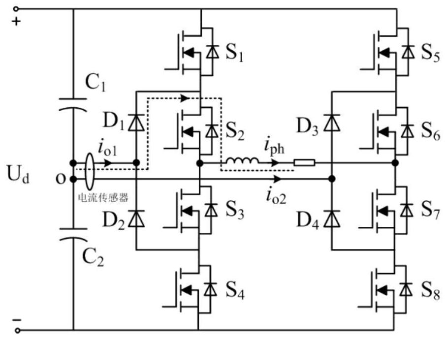
[0042] The topology of the neutral-point clamped single-phase three-level inverter is as follows: figure 1 As shown, among them, i ph is the phase current value, i o1 is the clamp current at the midpoint of the left bridge arm, i o2 is the midpoint clamping current of the right bridge arm, S 1 ~S 8 is the power triode, D 1 ~D 4 is the freewheeling diode, U d is the DC side voltage, C 1 and C 2 is the capacitor, o is the midpoint of the capacitor, and each phase bridge arm of the inverter is composed of four power transistors. The relationship between the midpoint clamp current of the two bridge arms and the current sensor current is as follows: figure 2 As shown, it is agreed that the positive direction of the reference current of the current sensor is from the inside to the outside, i o1 Penetrate the current sensor with one pass in the positiv...
PUM
 Abstract
Description
Claims
Application Information