Multi-mode broadband high-power directional transmitting longitudinal vibration underwater acoustic transducer

An underwater acoustic transducer and high-power technology, which is applied to transducers, sound-generating equipment, instruments and other directions used underwater, can solve the problems of difficult amplitude adjustment, large fluctuation of emission response, and low electro-acoustic efficiency. Achieve the effect of good fit, strong one-way radiation ability and small backward radiation

Pending Publication Date: 2021-03-19
THE 715TH RES INST OF CHINA SHIPBUILDING IND CORP
View PDF0 Cites 0 Cited by
  • Summary
  • Abstract
  • Description
  • Claims
  • Application Information

AI Technical Summary

Problems solved by technology

Dual-mode dual-resonance technology is an important technology to broaden the frequency band of longitudinal vibration transducers, but the broadband that such dual-mode longitudinal vibration transducers can obtain in the middle and low frequency bands is also limited, and the resonance points of the two resonance modes It is difficult to adjust the distribution and amplitude. There are usually response pits between the two resonant frequencies, resulting in large fluctuations in the emission response, usually above 5dB. The electro-acoustic efficiency is low at the response pits, and the acoustic power is insufficient.

Method used


Image

  • Multi-mode broadband high-power directional transmitting longitudinal vibration underwater acoustic transducer
  • Multi-mode broadband high-power directional transmitting longitudinal vibration underwater acoustic transducer
  • Multi-mode broadband high-power directional transmitting longitudinal vibration underwater acoustic transducer

Examples


Embodiment

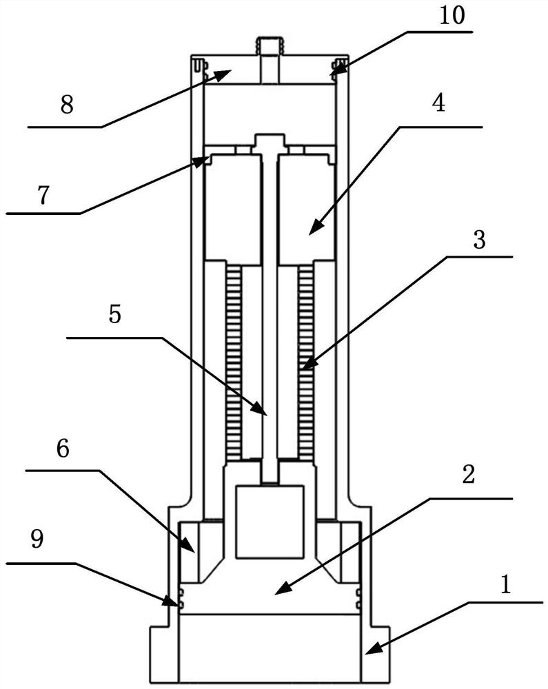
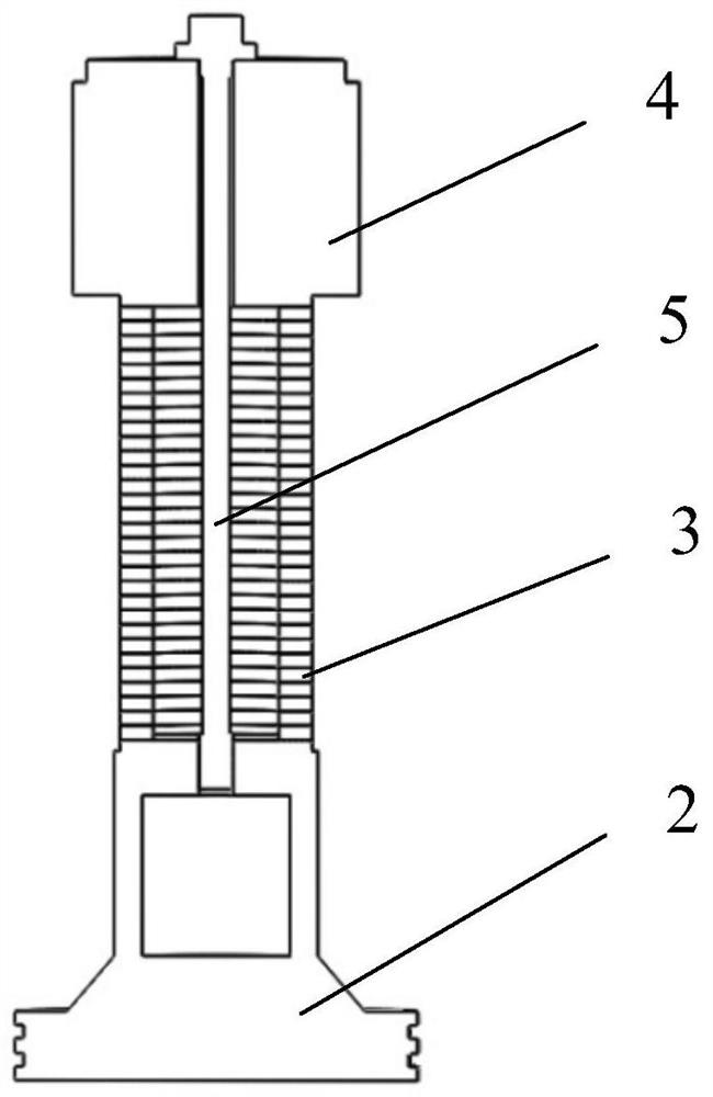
[0027] Example: as attached figure 1 As shown, this multi-mode broadband high-power directional emission longitudinal vibration underwater acoustic transducer includes a vibrator with a flexible ring longitudinal vibration transducer, a resonant cavity shell 1, a front cover and a rear decoupling support structure 6, and a rear cover The rear decoupling support structure 7 and the tail sealing end cover 8; the vibrator of the longitudinal vibration transducer with a flexible ring is composed of a front cover plate 2 with a flexible ring, a piezoelectric ceramic crystal stack 3, a stress screw 5 and a rear cover Plate 4 composition.

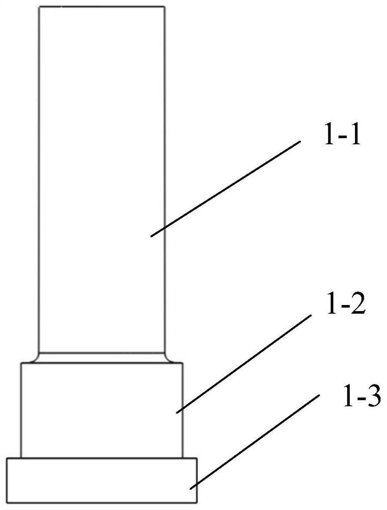
[0028] Such as figure 2 As shown, the resonant cavity shell 1 is made of corrosion-resistant metal materials such as stainless steel or titanium alloy. The resonant cavity shell 1 is a cylindrical structure with upper and lower openings and internal penetration, which includes a lower cylinder 1-2, a lower cylinder 1- 2. The diameter of the upp...


PUM


Abstract

The invention discloses a multi-mode broadband high-power directional transmitting longitudinal vibration underwater acoustic transducer, which relates to the field of underwater acoustic transducers,and comprises a longitudinal vibration transducer vibrator with a flexible ring, a square cylindrical structure resonant cavity shell, a decoupling support structure and a tail sealing end cover, wherein the longitudinal vibration transducer vibrator with the flexible ring is composed of a front cover plate with the flexible ring, a piezoelectric ceramic crystal pile, a stress screw rod and a rear cover plate. According to the liquid cavity coupling principle, a liquid coupling cavity in a square cylinder structure is designed at the front end of a front cover plate of a vibrator of the longitudinal vibration transducer with the flexible ring, and a new resonance peak can be generated between two resonances of the double-cover-plate longitudinal vibration transducer. The beneficial effects of the invention are that the multi-mode broadband high-power directional transmitting longitudinal vibration underwater acoustic transducer is wider in frequency band, and can achieve broadband transmission in a range of medium and low frequencies from 2.5 Hz to 7.5 Hz; backward radiation in a working frequency band is small, and the unidirectional radiation capacity is high; the structural size can be adjusted according to actual engineering requirements, and the deep-water working capacity, the adaptability and the flexible arrangement are achieved.

Description

technical field [0001] The invention relates to the field of underwater acoustic transducers, in particular to a multi-mode broadband high-power directivity emitting longitudinal vibration underwater acoustic transducer. Background technique [0002] Longitudinal vibration transducers, also known as Tonpilz transducers, are widely used in the field of underwater acoustic transducers due to their simple structure and stable performance. The transmitting working bandwidth of the transducer affects the overall performance of the active sonar, such as the amount of information in the echo, the transmission rate of the signal, and the ability to resist reverberation. [0003] Active sonar is a device that emits sound waves into the water. In order to make sound waves travel farther and obtain better emission effects, multiple underwater acoustic transducers are usually used to form a sound-emitting array to achieve high-power directional emission. Active sonar emission arrays us...

Claims


Application Information

Patent Timeline
Patent Type & Authority Applications(China)
IPC IPC(8): G10K9/122H04R1/44
CPCG10K9/122H04R1/44
Inventor 刘强李坚赵圣尉赵天吉刘佳俊朱强徐璐沈铁东
Owner THE 715TH RES INST OF CHINA SHIPBUILDING IND CORP
Why Eureka
Try Eureka