
Forming device for spacecraft fairing production

A molding device and fairing technology, applied in the aerospace field, can solve the problems of increased assembly time, large quality, large volume, etc., and achieve the effects of convenient work, convenient adjustment, and convenient assembly work.

Inactive Publication Date: 2021-03-23
李志杰
View PDF1 Cites 0 Cited by
  • Summary
  • Abstract
  • Description
  • Claims
  • Application Information

AI Technical Summary

Problems solved by technology

But this device has the following disadvantages: 1. The device has a large volume and a high quality. When it is produced with a common punch press, it is inconvenient to move the device, which increases the assembly time.

Method used


Image

  • Forming device for spacecraft fairing production
  • Forming device for spacecraft fairing production
  • Forming device for spacecraft fairing production

Examples


Embodiment 1

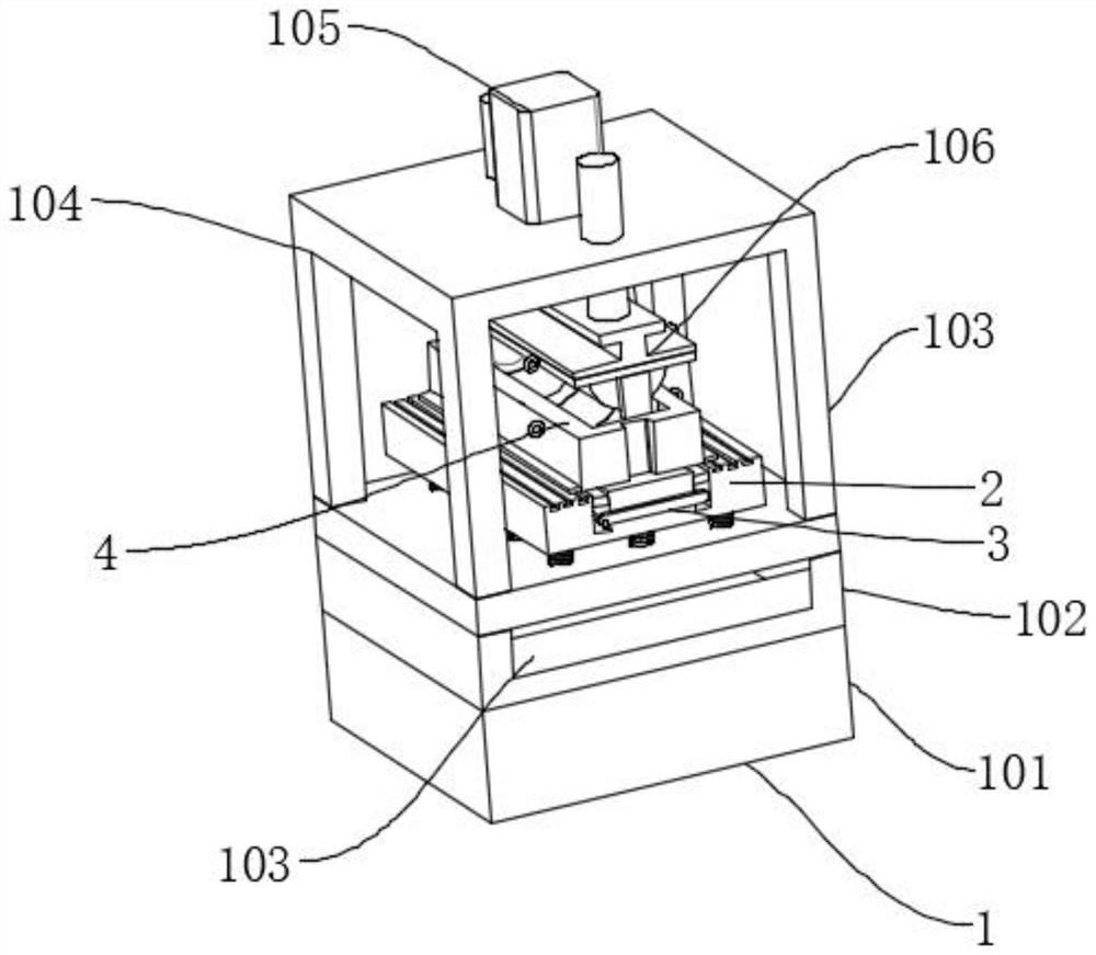
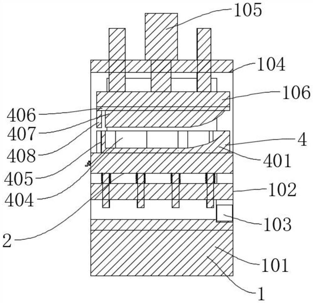
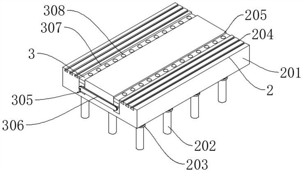
[0034] Such as Figure 1-7As shown, a molding device for the production of spacecraft fairings includes a molding mechanism 1 and a molding die 4. The molding mechanism 1 is mainly composed of a base 101, a mounting frame 102, a frame 104, a hydraulic cylinder 105, and a pressing plate 106. , the top of the base 101 is fixedly installed with an installation frame 102, the top of the installation frame 102 is connected with a frame 104 by bolts, the top of the frame 104 is connected with a hydraulic cylinder 105 by bolts, and the output end of the hydraulic cylinder 105 is connected with a pressure plate 106 by bolts. The frame 102 is a back-type structure, and the top is provided with several through holes 1021, and the front end of the mounting frame 102 is rotatably connected with a storage box 103, so that the storage box 103 can be used to store tools and work notebooks, which facilitates work and saves time. Including a support mechanism 2, the support mechanism 2 include...

Embodiment 2

[0036] Such as Figure 8 As shown, the difference between Embodiment 2 and Embodiment 1 is that the pressing plate 106 adopts an I-shaped structure, the two ends of the top of the pressing plate 106 are connected with the front body guide column 11 by screws, and the upper end of the front body guide column 11 passes through the frame 104, and Slidingly connected with the frame 104, such setting increases the strength and stability of the pressing plate 106.

[0037] In the above structure, when in use, the hydraulic cylinder 105 can be activated, the hydraulic cylinder 105 drives the pressing plate 106 to descend, the pressing plate 106 drives the connecting plate 406 to descend, the connecting plate 406 drives the forming convex body 407 to descend, and the forming convex body 407 squeezes the material, so that the material Molding in the cavity between the molding convex body 407 and the molding groove 404, when assembling the molding mold 4, first use the crane to lift the...


PUM


Abstract

The invention discloses a forming device for spacecraft fairing production. The forming device comprises a profiling mechanism and a forming mold, the profiling mechanism is mainly composed of a base,a mounting frame, a rack, a hydraulic cylinder and a pressing plate, the mounting frame is fixedly mounted at the top of the base, the top of the mounting frame is connected with the rack through bolts, and the top of the rack is connected with the hydraulic cylinder through bolts. By rotating a crank, the crank drives a chain set to rotate, the chain set drives two driving rods to rotate, the driving rods drive a scissor jack to ascend, the scissor jack jacks up a top plate, and the top plate drives balls to ascend, so that the tops of the balls are higher than the height of a supporting table; the balls and the top plate are in rolling connection, therefore, the forming mold can be pushed with small force, the position of the forming mold is adjusted conveniently, the forming mold can be assembled conveniently, and the forming mold can further be fixed through a T-shaped groove, a T-shaped block and the pressing plate.

Description

technical field [0001] The invention relates to the field of aerospace technology, in particular to a molding device used for producing spacecraft fairings. Background technique [0002] A spacecraft is composed of an instrument cabin, an engine, and a control system. When a spacecraft flies in the atmosphere at high speed, the oncoming airflow meets the spacecraft cabin and is suddenly compressed, and the local airflow is blocked. At the same time, the air flow and the cabin body There is also friction on the surface, which increases the temperature of the surface of the cabin, causing aerodynamic heating. In order to protect the cables across the cabin on the outer surface, fairings are often used for protection. The fairing is located on the protruding part of the outer surface of the cabin, and the aerodynamic heating is more serious than other parts. At the same time, there are various telemetry equipment and control cables installed inside the fairing. When the cabin ...

Claims


Application Information

Patent Timeline
IPC IPC(8): B21D37/10
CPCB21D37/10
Inventor 李志杰刘思宇
Owner 李志杰
Learn More