Manufacturing method of ramp steel box girder

A manufacturing method and technology of steel box girders, which are applied in the field of steel box girder manufacturing, can solve problems such as difficult control of welding deformation, difficulty in connecting beam sections, and difficulty in blanking, so as to achieve the effect of eliminating welding deformation

Inactive Publication Date: 2021-03-23
洛阳豫安金属结构有限公司
View PDF7 Cites 8 Cited by
  • Summary
  • Abstract
  • Description
  • Claims
  • Application Information

AI Technical Summary

Problems solved by technology

[0003] 1. It is difficult to cut the material, most of the blanking boards are not a common rectangle;
[0004] 2. It is difficult to form, especially the forming shape of the bridge body is difficult to meet the design requirements;
[0005] 3. Welding deformation is difficult to control;
[0006] 4. It is difficult to realize the docking between the beam segments
If the application of steel box girders on ramp approach bridges cannot be realized, the development and application of steel box girder bridges will be severely restricted. Therefore, a new manufacturing method for ramp steel box girders is needed to overcome the above difficulties

Method used


Image

  • Manufacturing method of ramp steel box girder
  • Manufacturing method of ramp steel box girder

Examples


Embodiment Construction

[0034] Preferred embodiments of the present invention are described below with reference to the accompanying drawings. Those skilled in the art should understand that these embodiments are only used to explain the technical principles of the present invention, and are not intended to limit the protection scope of the present invention.

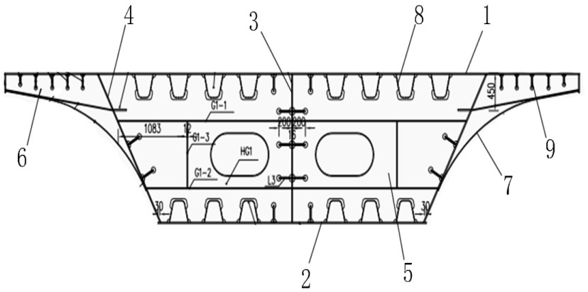
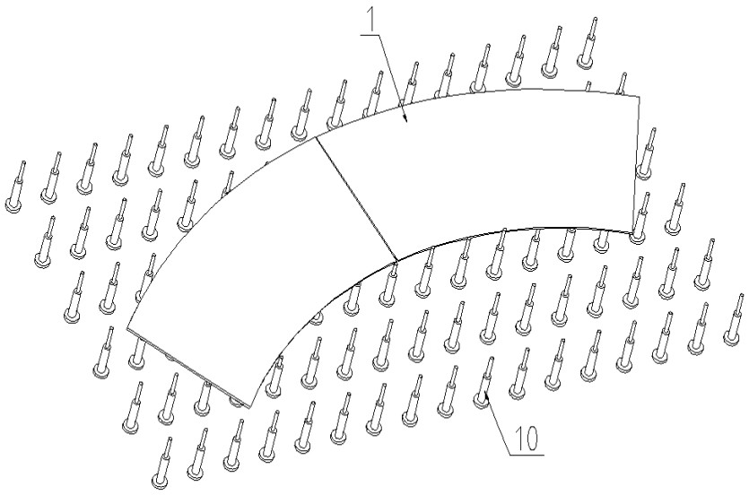
[0035] In a bridge construction project, the main bridge adopts a long-span steel box girder structure. In order to maintain the consistency of the bridge body connection, the ramp approach bridges at both ends of the bridge also adopt a steel box girder structure. figure 1 As shown, the ramp steel box girder includes a bridge deck 1 , a bottom deck 2 , a middle web 3 , a side web 4 , a diaphragm 5 , a cantilever plate 6 and a decorative plate 7 . The ramp steel box girder has a spiral shape as a whole. For the convenience of manufacture and installation, the ramp steel box girder is manufactured in sections.

[0036] A method for manufacturi...


PUM


Abstract

The invention relates to a manufacturing method of a ramp steel box girder. The manufacturing method comprises the following steps that segmented modeling is performed on the ramp steel box girder byusing three-dimensional modeling software, and components on each bridge segment are lofted to determine the cutting shape of each component; and a plurality of height-adjustable supporting columns are arranged in a tailor-welded area in an array mode, modeling is conducted on a supporting column array on the three-dimensional modeling software, and the distance between each supporting column anda bridge deck slab is obtained to determine the supporting height of each supporting column, so that the bending shape of the plate face of the spliced bridge deck slab is made to be the same as the bending shape of the road face of a designed ramp. According to the manufacturing method of the ramp steel box girder, accurate discharging of all components is achieved, overturning and positioning ofall sections of bridge deck slabs are achieved through the supporting columns, and it is guaranteed that the forming shape of the bridge deck meets the design requirement; the deformation area is corrected in advance, the influence of welding deformation on the whole is eliminated, and rapid butt joint of construction sites is achieved by reserving the positioning matching parts; and the application of the steel box girder to ramp approach bridges is realized, and the development of the steel box girder in the field of bridges is facilitated.

Description

technical field [0001] The invention relates to the field of manufacturing steel box girders, in particular to a method for manufacturing ramp steel box girders. Background technique [0002] Steel box girders are mainly used in the construction of main bridges. Compared with cement box girders, they have the advantages of large load capacity and high earthquake resistance. However, for the ramp approach bridges at both ends of the main bridge, the cement box girder has more advantages, because the bridge body of the ramp is a spiral body with a complex shape. For cement box girders, it can be poured after the mold is manufactured in sections according to the design drawings. The shape of the bridge deck and the interface of the beam end depend on the design of the mold, which is easy to realize; while for the steel box girder , it is easy to manufacture a straight main bridge, but it is very difficult to manufacture a ramp approach bridge with a complex shape, specifically...

Claims


Application Information

Patent Timeline
Patent Type & Authority Applications(China)
IPC IPC(8): B23K31/02B23K37/04E01D2/04E01D101/30
CPCB23K31/02B23K37/0426E01D2/04E01D2101/30
Inventor 黄克政朱建洛赵济乐狄亚飞温振营刘涛涛丁信豹郑阳阳孙文飞
Owner 洛阳豫安金属结构有限公司
Why Eureka
Try Eureka