Beam plate correcting device for fabricated building

An architectural and prefabricated technology, applied in the construction, building structure, construction material processing and other directions, can solve the problems of excessive weight, offset installation position, limited manpower, etc., to improve assembly efficiency, reduce friction, The effect of improving continuity and strength

Active Publication Date: 2021-03-23
广元市永昌建设有限公司
View PDF5 Cites 4 Cited by
  • Summary
  • Abstract
  • Description
  • Claims
  • Application Information

AI Technical Summary

Problems solved by technology

[0004] Prefabricated beams and slabs are prefabricated components in which beams and slabs are integrated, and they are jointly stressed and deformed. Unlike cast-in-place beams and slabs, prefabricated beams and slabs are prefabricated in the prefabricated field and then transported to the construction site for construction. However, due to the heavy weight of prefabricated beams and slabs, it is often assembled manually by tower cranes. On the one hand, it is difficult to achieve precise control of tower cranes, resulting in serious deviations in the installation position. On the other hand, limited manpower makes it difficult to effectively Correction of prefabricated slabs is also prone to safety accidents. In summary, the current assembly efficiency of prefabricated beams and slabs is extremely low, and the assembly effect is poor, often requiring a secondary correction process, which seriously delays the overall construction efficiency of prefabricated buildings.

Method used


Image

  • Beam plate correcting device for fabricated building
  • Beam plate correcting device for fabricated building
  • Beam plate correcting device for fabricated building

Examples


Embodiment 1

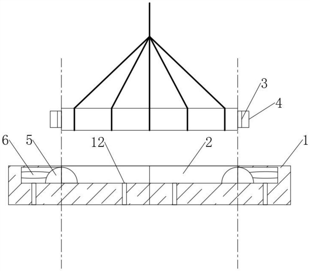
[0041] See figure 1 One assembly building beam coil correction device, including correcting mold 1 and beam plate, and the upper end of the correcting mold 1 is opened with the beam plate phase matching, and there is a avoidance groove on the side wall of the correcting groove 2, the avoidance groove The sliding connection has a phase-matched correction half-pillar 5, and the correction half-column 5 is connected between the side walls of the avoidance groove, and the area of ​​the beam plate corresponds to the regions of the column 5, and the vacuum suction cup 3 is connected to the vacuum suction cup 3. The magnet block 4 is connected, and the magnetogenic coordination is imparted by the specific area of ​​the beam plate, and the vacuum chuck 3 and magnet block 4 can be removed when the initial correction is successfully fallen to the correction mold 1.

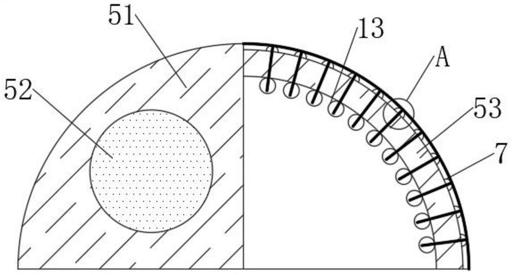
[0042] See figure 2 The corrected semi-column 5 includes a balance post 51, an electromagnet 52, and a correction column 53...


PUM


Abstract

The invention discloses a beam plate correcting device for a fabricated building, belongs to the technical field of fabricated buildings, and aims to realize preliminary correction during hoisting byadsorbing a magnet block on a beam plate based on a vacuum chuck and then applying a magnetic field guiding effect on the beam plate by utilizing a correcting semi-column on a correcting mold. The beam plate is forced to basically align to the correcting groove in the correcting mold to fall off, then the correcting action can be automatically triggered by utilizing the inclination characteristicthrough the spherical surface sensing effect of the correcting semi-column, the beam plate can continuously extrude the correcting semi-column to avoid under the action of gravity, and meanwhile, thebeam plate also slowly descends and finally enters the correcting groove after being corrected. Compared with the prior art, the self-correcting device has the advantages that the contact surface of the correcting semi-column is subjected to anti-abrasion protection in an ice condensation mode in the extrusion process, on one hand, the correcting semi-column is subjected to anti-abrasion protection, on the other hand, the friction force between the beam plate and the correcting semi-column is reduced, and compared with the prior art, the self-correcting effect on the prefabricated beam plate can be achieved, and assembling efficiency is greatly improved.

Description

Technical field [0001] The present invention relates to the field of assembling construction technology, and more particularly to a beam coil correction device for assembling construction. Background technique [0002] Assembly buildings refer to the transfer of large number of live operations in traditional construction methods to the factory, producing construction components and accessories in factory (such as floor board, wall panel, stairs, balcony, etc.), transportation to the construction site, pass through Reliable connection is installed on site. [0003] The assembled building mainly includes prefabricated assembled concrete structures, steel structures, modern wood structural buildings, because of the use of standardized design, factory production, assembly construction, information management, intelligent application, is a representative of modern industrial production. [0004] The prefabricated beam plate is a prefabricated member of a beam and board as a whole, and...

Claims


Application Information

Patent Timeline
Patent Type & Authority Applications(China)
IPC IPC(8): E04G21/18
CPCE04G21/1841
Inventor 姜婧
Owner 广元市永昌建设有限公司
Why Eureka
Try Eureka