Backlight module, backlight module manufacturing method and display panel

A backlight module and display panel technology, which is applied in optics, nonlinear optics, instruments, etc., can solve the problems of reducing the smoothness and reliability of the white reflective layer, increasing the difficulty of bonding the white reflective layer, and bad light shadows, etc., so as to avoid display Effects of dark spots, difficulty reduction, and flattening

Active Publication Date: 2021-03-23
TCL CHINA STAR OPTOELECTRONICS TECH CO LTD
View PDF12 Cites 2 Cited by
  • Summary
  • Abstract
  • Description
  • Claims
  • Application Information

AI Technical Summary

Problems solved by technology

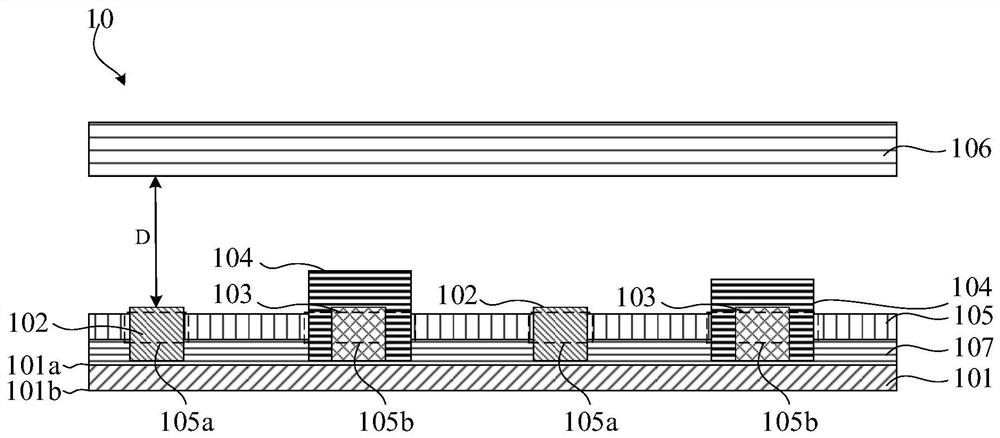
[0003] After the backlight is completed, the module needs to be assembled. Generally, in order to improve the utilization rate of the backlight, a white reflective layer (reflectivity > 95%) will be pasted on the surface of the mini-LEDBLU. The white reflective layer is usually pasted manually. The minimum cutting aperture is 3mm, and the LED will be exposed at the incision, so that the LED emits light; but because the MOS does not emit light, and the exposed MOS is easy to cause mura, that is, the dark area above, so the white reflective layer The MOS will be covered below, so the white reflective layer is raised at the MOS on the entire backplane, which increases the difficulty of laminating the white reflective layer on the one hand, and reduces the flatness and reliability of the white reflective layer on the other hand

Method used


Image

  • Backlight module, backlight module manufacturing method and display panel
  • Backlight module, backlight module manufacturing method and display panel
  • Backlight module, backlight module manufacturing method and display panel

Examples


Embodiment Construction

[0040] The technical solutions in the embodiments of the present application will be clearly and completely described below in conjunction with the drawings in the embodiments of the present application. Apparently, the described embodiments are only some of the embodiments of this application, not all of them. Based on the embodiments in this application, all other embodiments obtained by those skilled in the art without making creative efforts belong to the scope of protection of this application.

[0041] It should be noted that in the description of the present application, it should be understood that the terms "upper", "lower", "front", "rear", "left", "right", "inner", "outer", etc. The indicated orientation or positional relationship is based on the orientation or positional relationship shown in the drawings, and is only for the convenience of describing the present application and simplifying the description, rather than indicating or implying that the referred devic...


PUM

PropertyMeasurementUnit
reflectanceaaaaaaaaaa

Abstract

The embodiment of the invention provides a backlight module, a backlight module manufacturing method and a display panel. The backlight module comprises an array substrate, a light emitting diode, a driving switch, a reflection packaging glue and a reflection layer. According to the invention, a reflecting layer is provided with a first through hole and a second through hole at a light emitting diode and a driving switch respectively, and a reflecting packaging adhesive is adopted at the driving switch for packaging, so that the driving switch can be further reinforced so as to improve the reliability of the driving switch, the reflectivity of the reflection packaging adhesive is high, and light reflected by the driving switch can be reflected back so as to avoid display dark spots; and when the reflecting layer is attached, the first through hole and the second through hole are formed in the light-emitting diode and the driving switch respectively, so that the light-emitting diode andthe driving switch are completely exposed, attachment is smoother, the attachment difficulty of the reflecting layer is reduced, and the attachment reliability of the reflecting layer is enhanced.

Description

technical field [0001] The present application relates to the field of display technology, in particular to a backlight module, a backlight module manufacturing method, and a display panel. Background technique [0002] The Mini-LED backlight module (Backlight unit, BLU) is a backlight design that realizes partition control. It is a light-emitting diode chip (LED chip) and a drive switch (MOS) that are printed one by one through the surface mount technology (Surface Mounted Technology, SMT) process. key to the BLU backboard to realize the assembly of the mini-LED backlight, so the MOS and LED chip are raised on the entire backlight. [0003] After the backlight is completed, the module needs to be assembled. Generally, in order to improve the utilization rate of the backlight, a white reflective layer (reflectivity > 95%) will be pasted on the surface of the mini-LEDBLU. The white reflective layer is usually pasted manually. The minimum cutting aperture is 3mm, and the L...

Claims


Application Information

Patent Timeline
Patent Type & Authority Applications(China)
IPC IPC(8): G02F1/13357
CPCG02F1/133605G02F1/133603
Inventor 彭钊刘俊领吴思嘉
Owner TCL CHINA STAR OPTOELECTRONICS TECH CO LTD
Why Eureka
Try Eureka