
Light emission driver and display device having same

A driver and stabilizer technology, applied in the direction of instruments, static indicators, etc., to shorten the fall time, improve the drive reliability, and eliminate the fall stage.

Pending Publication Date: 2021-03-23
SAMSUNG DISPLAY CO LTD
View PDF1 Cites 2 Cited by
  • Summary
  • Abstract
  • Description
  • Claims
  • Application Information

AI Technical Summary

Problems solved by technology

Due to the fast driving frequency, the time for compensating the threshold voltage of the driving transistor of the pixel and the data writing time may be insufficient

Method used


Image

  • Light emission driver and display device having same
  • Light emission driver and display device having same
  • Light emission driver and display device having same

Examples


Embodiment approach

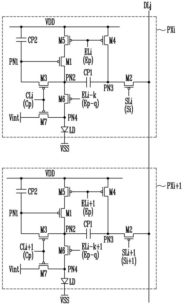
[0063] According to some example embodiments, all of the first to seventh transistors M1 to M7 may be the same type of transistors. For example, the first to seventh transistors M1 to M7 may be P-channel metal oxide semiconductor (PMOS) transistors. The first to seventh transistors M1 to M7 may include active layers formed of a polysilicon semiconductor. For example, active layers of the first to seventh transistors M1 to M7 may be formed through a low temperature polysilicon (LTPS) process. However, this is an example, and according to some exemplary embodiments, at least one of the first to seventh transistors M1 to M7 (or all of the first to seventh transistors M1 to M7 ) may be an N-channel metal oxide Semiconductor (NMOS) transistors. For example, an NMOS transistor may include an active layer formed of an oxide semiconductor.

[0064] Hereinafter, for convenience of description, the pixel configuration and operation will be described with reference to the pixel PXi of...


PUM


Abstract

The present invention provides a light emission driver and a display device having the same. The light emission driver includes a plurality of stages outputs a light emission control signal. Each of the stages includes an input circuit controlling voltages of a first node and a second node, an output circuit supplying a voltage of first power or a second power to an output terminal, a first signalprocessor controlling a voltage of a fourth node based on a signal supplied to a third input terminal and a voltage of a fifth node, a second signal processor controlling the voltage of the fourth node in response to the voltage of a third node, a first stabilizer limiting voltage drops of the first node and the second node, and a second stabilizer controlling an electrical connection between thethird node and the first node in response to the voltage of the fourth node.

Description

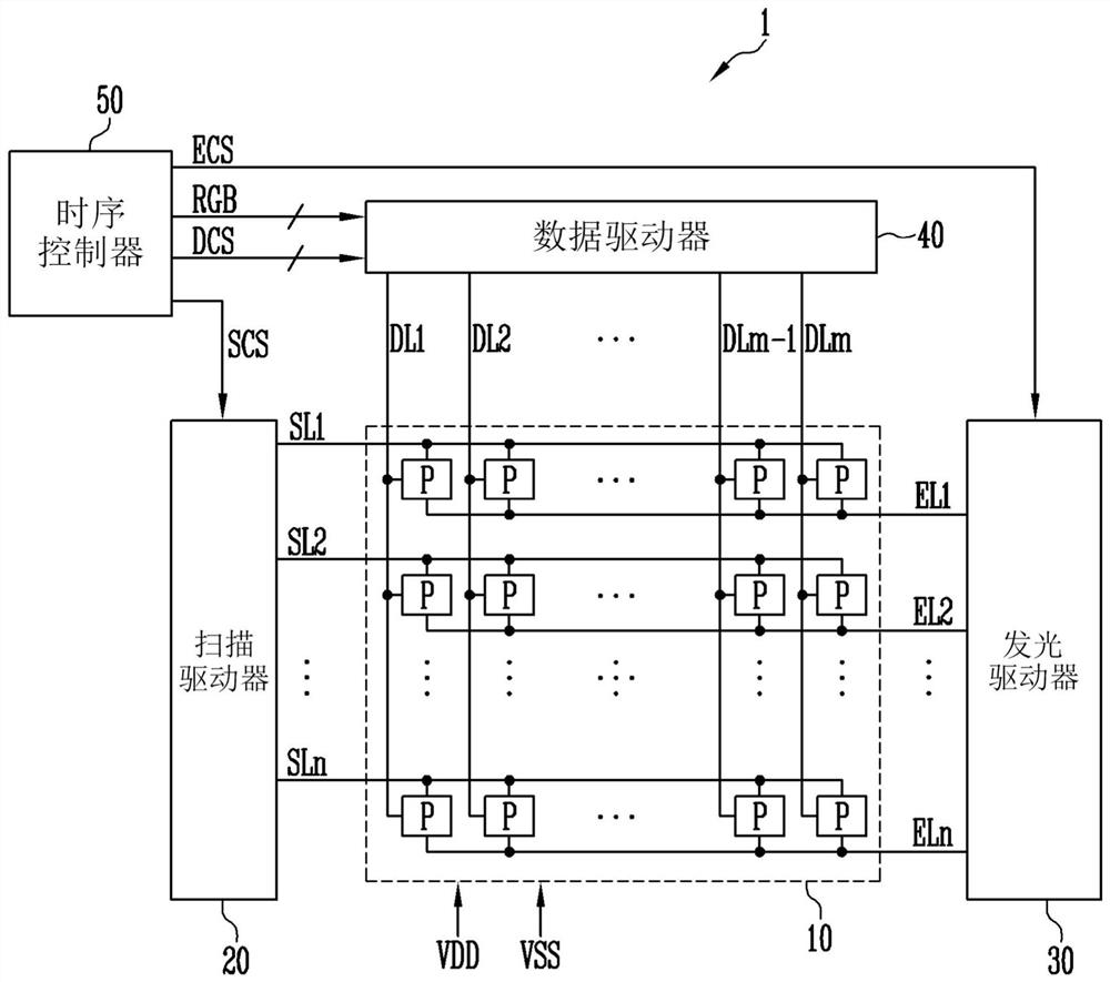
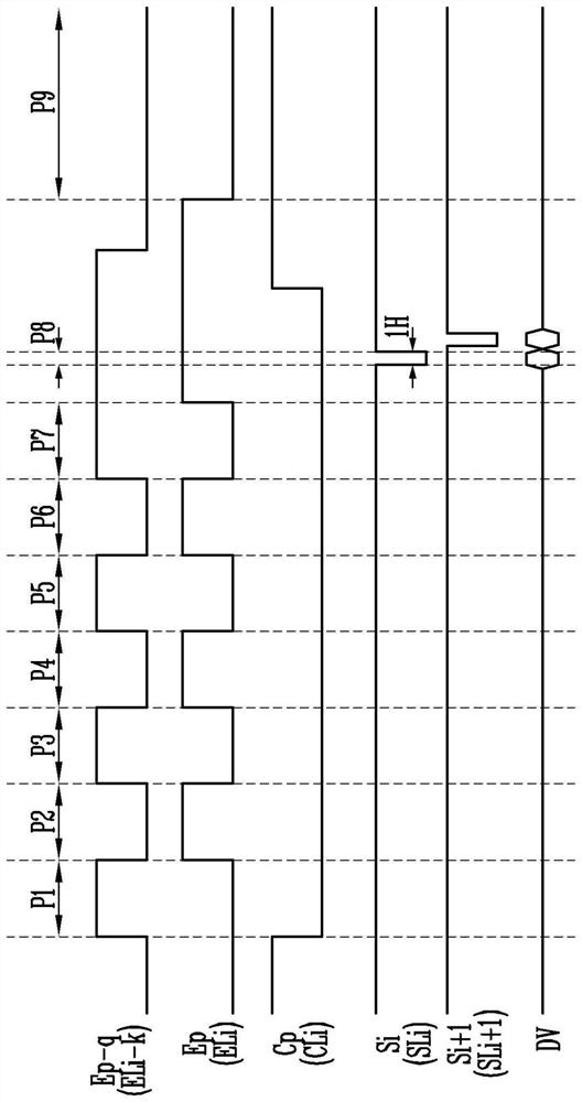
[0001] Cross References to Related Applications [0002] This application claims priority and benefit from Korean Patent Application No. 10-2019-0110141 filed on September 5, 2019, the contents of which are hereby incorporated by reference in their entirety. technical field [0003] Aspects of some example embodiments of the present disclosure relate to a display device. Background technique [0004] A display device generally includes a data driver for supplying data signals to the data lines, a scan driver for supplying scan signals to the scan lines, a light emission driver for supplying light emission control signals to the light emission control lines, and a data driver positioned to connect to the data lines. Lines, Scan Lines, and Luminescence Control Lines. [0005] Here, the light emitting time of the pixel may be controlled by a light emitting control signal supplied from a light emitting driver. To this end, the light emission driver may include a stage connecte...

Claims


Application Information

Patent Timeline
Patent Type & Authority Applications(China)
IPC IPC(8): G09G3/32G09G3/3208
CPCG09G3/32G09G3/3208G09G2310/0264G09G3/2092G09G3/3266G09G3/3233G09G3/3225G09G2300/0819G09G2300/0814G09G2300/0842G09G2300/0861G09G2310/0267G09G2310/0286G09G2310/0281G09G2310/08G09G2320/0252G09G2310/06G09G2230/00G09G3/3258G09G2300/0426G09G3/3275
Inventor 朴埈贤具本龙李柔辰郑京薰
Owner SAMSUNG DISPLAY CO LTD
Learn More