Cerebrospinal fluid drainage device and method

A cerebrospinal fluid and drainage tube technology, which is applied in the field of medical devices, can solve the problems of stretching of the drainage pipeline, complex structural design, and a lot of data collection, and achieves the effects of high pressure and speed control accuracy, reliable products, and convenient use.

Pending Publication Date: 2021-03-26
CHANGCHUN INST OF OPTICS FINE MECHANICS & PHYSICS CHINESE ACAD OF SCI +1
View PDF3 Cites 1 Cited by
  • Summary
  • Abstract
  • Description
  • Claims
  • Application Information

AI Technical Summary

Problems solved by technology

At the same time, during the drainage process, because the patient is generally in a state of unconsciousness, he will turn over uncontrollably and other activities, which is particularly easy to cause the stretching of the drainage tube, which will cause the position of the drainage tube in the patient's brain to change. Then affect the drainage effect and increase the difficulty of patient care
In the existing cerebrospinal fluid drainage process, in order to balance the intracranial pressure, the medical staff need to constantly adjust the height of the drainage pot to maintain the drainage speed and height of the cerebrospinal fluid or hematoma, which increases the complexity of the medical staff's operation and the number of medical staff.
[0005

Method used


Image

  • Cerebrospinal fluid drainage device and method
  • Cerebrospinal fluid drainage device and method
  • Cerebrospinal fluid drainage device and method

Examples


Embodiment Construction

[0050] In order to make the purpose, technical solution and advantages of the present application clearer, the technical solution of the present application will be clearly and completely described below in conjunction with specific embodiments of the present application and corresponding drawings. Apparently, the described embodiments are only some of the embodiments of the present application, rather than all the embodiments.

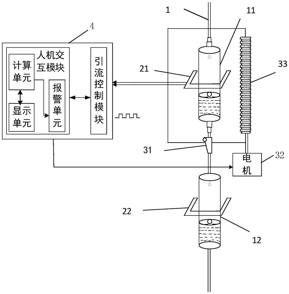
[0051] figure 1 It is a structural schematic diagram of a preferred embodiment of the cerebrospinal fluid drainage device of the present application, including a drainage tube 1 , a flow rate sensor 2 , a flow regulator (not shown) and a drainage control system 4 .

[0052] The drainage circuit 1 includes a drainage tube and drainage bags 11 and 12 communicating with the drainage tube and used for temporarily storing cerebrospinal fluid. A certain amount of cerebrospinal fluid is stored in the drainage bag to prevent backflow of cerebrospinal fluid. ...


PUM


Abstract

The invention discloses a cerebrospinal fluid drainage device and method. The cerebrospinal fluid drainage device comprises a drainage tubeline, a flow velocity sensor, a flow regulator and a drainagecontrol system, wherein the drainage control system comprises a man-machine interaction module and a drainage control module; the man-machine interaction module is used for inputting an expected flowvelocity/flow velocity range and an expected drainage amount, recording and displaying patient personal information, treatment information, a historical cerebrospinal fluid flow velocity and a current cerebrospinal fluid flow velocity, and judging a drainage state according to the current cerebrospinal fluid drainage amount and a real-time fluid flow velocity; and the drainage control module controls the flow regulator according to the current drainage state so as to enable the real-time fluid flow velocity to be equal to the expected flow velocity or fall into the expected flow velocity range or controls the current drainage to be paused/ended. The cerebrospinal fluid drainage device is simple in structure, automatic pressure and velocity regulation of automatic cerebrospinal fluid drainage can be achieved by directly improving a traditional cerebrospinal fluid drainage device, the pressure and velocity control precision is high, the product is reliable, and the use is convenient.

Description

technical field [0001] The present application relates to the field of medical devices, in particular to a cerebrospinal fluid drainage device and a drainage method. Background technique [0002] In clinical practice, external drainage of cerebrospinal fluid is a safe, effective, and minimally invasive method for treating neurosurgical diseases such as cerebrospinal fluid leakage, intracranial infection, and subarachnoid hemorrhage; Hemorrhage, various intractable cerebrospinal fluid otorrhea, rhinorrhea, incision leakage, intracranial infection, intractable subcutaneous effusion, and communicating hydrocephalus all have good curative effects. [0003] External drainage of cerebrospinal fluid refers to placing a drainage tube into the ventricle to continuously draw out cerebrospinal fluid. First, it can reduce intracranial pressure, and second, it can promote the discharge of inflammatory cerebrospinal fluid, so as to clean the cerebrospinal fluid and assist in the treatment...

Claims


Application Information

Patent Timeline
IPC IPC(8): A61M1/00
CPCA61M2205/18A61M2205/3327A61M2205/3334
Inventor 田大鹏王昱棠王中石王福超贾平王光明
Owner CHANGCHUN INST OF OPTICS FINE MECHANICS & PHYSICS CHINESE ACAD OF SCI
Why Eureka
Try Eureka