
Automatic equipment for welding U-shaped hoop and flat head pin and welding method thereof

A pin and U-shaped technology, which is applied to the automation equipment and welding field of U-shaped hoop and flat-head pin welding, can solve the problems of low automation, low production efficiency, and high risk factor, so as to improve the automation and reduce the man-hours , the effect of high safety factor

Active Publication Date: 2021-03-26
JIANGSU UNIV OF SCI & TECH
View PDF8 Cites 5 Cited by
  • Summary
  • Abstract
  • Description
  • Claims
  • Application Information

AI Technical Summary

Problems solved by technology

[0007] Purpose of the invention: In order to overcome the deficiencies in the prior art, provide an automatic equipment and welding method for welding U-shaped hoops and flat-head pins, which realizes the automatic welding of U-shaped hoops and flat-head pins in a short time Material, assembly, welding and blanking solve the problems of low automation, low production efficiency, high labor cost and high risk factor in the welding of U-shaped hoops and flat-headed pins, which greatly improves the production capacity of the overall assembly line and reduces Labor cost, degree of automation and intelligence have all been significantly improved

Method used


Image

  • Automatic equipment for welding U-shaped hoop and flat head pin and welding method thereof
  • Automatic equipment for welding U-shaped hoop and flat head pin and welding method thereof
  • Automatic equipment for welding U-shaped hoop and flat head pin and welding method thereof

Examples


Embodiment Construction

[0057] Below in conjunction with accompanying drawing and specific embodiment, further illustrate the present invention, should be understood that these embodiments are only for illustrating the present invention and are not intended to limit the scope of the present invention, after having read the present invention, those skilled in the art will understand various aspects of the present invention Modifications in equivalent forms all fall within the scope defined by the appended claims of this application.

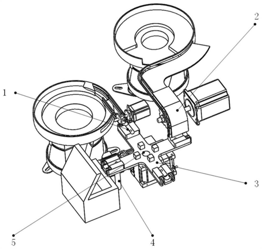
[0058] Such as figure 1 As shown, the present invention provides an automatic equipment for welding U-shaped hoops and flat-head pins, including a feeding device, a workpiece unloading device 4 and a four-station rotary table 5; wherein,

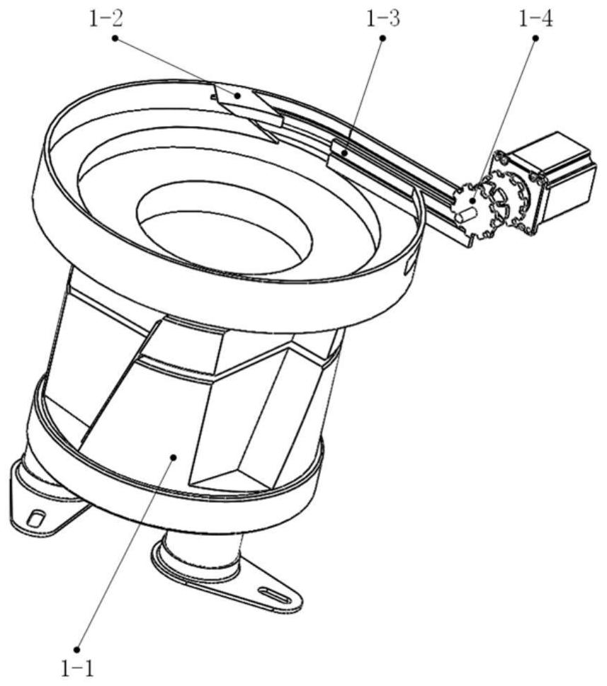
[0059] The feeding device includes a U-shaped hoop feeding device 1 and a flat-head pin feeding device 2, and a U-shaped hoop feeding device 1 and a flat-head pin feeding device 2 are respectively used for sorting and conveying of U-sh...


PUM


Abstract

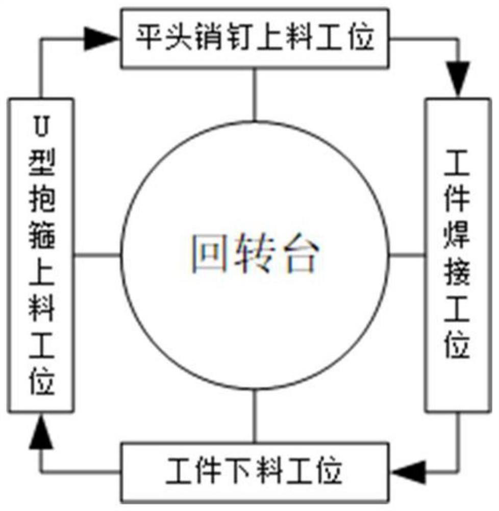
The invention discloses automatic equipment for welding a U-shaped hoop and a flat head pin and a welding method of the automatic equipment. The equipment comprises a feeding device, a discharging device and a four-station rotary workbench; the feeding device comprises a U-shaped hoop feeding device and a flat head pin feeding device, and the U-shaped hoop feeding device and the flat head pin feeding device are used for sorting and conveying U-shaped hoops and flat head pins respectively; the discharging device is used for collecting the welded U-shaped hoop and the flat head pin; and the U-shaped hoop feeding device, the flat head pin feeding device, the discharging device and a welding machine are arranged on the four sides of the four-station rotary workbench respectively to form four stations, and the four-station rotary workbench is used for achieving conversion of the four stations. According to the automatic equipment, automatic feeding, assembling, welding and discharging of the U-shaped hoop and the flat head pin within a short time are realized, the production capacity of the whole assembling production line is greatly improved, the labor cost is reduced, and the automation degree and the intelligent degree are obviously improved.

Description

technical field [0001] The invention belongs to the field of welding technology, and relates to an automatic welding method and equipment, in particular to an automatic equipment and a welding method for welding U-shaped hoops and flat pins. Background technique [0002] U-shaped hoops and flat-head pins have the characteristics of small size, large quantity, and complex structure, and there are problems of assembly and welding difficulties during production. The traditional production method is still dominated by small workshops, completely dependent on manual labor, and its main production process is as follows: manual sorting, manual assembly, manual welding, manual unloading, and the production process is still at a backward stage. [0003] There are following problems in this technique: [0004] 1) After the assembly is completed, manual support is required to maintain the assembled state of the workpiece before welding, which does not guarantee the safety of the opera...

Claims


Application Information

Patent Timeline
Patent Type & Authority Applications(China)
IPC IPC(8): B23K37/00B23K37/04B23K31/02
CPCB23K37/00B23K37/0426B23K31/02
Inventor 方喜峰孙浩然张胜文龚婵媛张辉朱成顺朱鹏程程德俊徐圣昊
Owner JIANGSU UNIV OF SCI & TECH
Learn More