Spunlace non-woven fabric cleaning agent soaking processing device
A technology of spunlace non-woven fabrics and processing devices, which is applied in liquid/gas/steam processing transmission devices, textiles and papermaking, and textile material processing, etc., which can solve unfavorable production and development of enterprises, low work efficiency, and large manpower consumption and other problems, to achieve the effect of increasing the wetted area, reducing manpower, and reducing the trouble of collecting spunlace nonwovens
- Summary
- Abstract
- Description
- Claims
- Application Information
AI Technical Summary
Problems solved by technology
Method used
Image
Examples
Embodiment 1
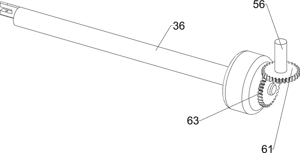
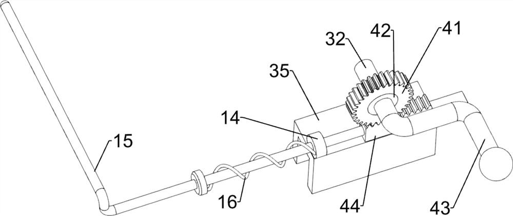
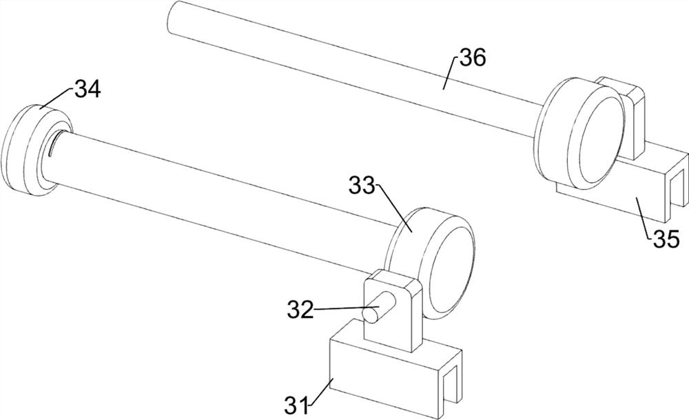
[0027] A spunlace non-woven cleaning agent wets processing equipment such as Figure 1 to Figure 5 As shown, it includes a support frame 1, a cylinder body 2, a placement assembly 3, a steering assembly 4, a drive assembly 5 and a rotation assembly 6. The support frame 1 is provided with a cylinder body 2, and the upper side of the cylinder body 2 is provided with a placement assembly 3 , The placement assembly 3 is provided with a steering assembly 4 , the upper right side of the cylinder body 2 is provided with a drive assembly 5 , and the drive assembly 5 is provided with a rotation assembly 6 .
[0028] When the spunlace non-woven fabric needs to be soaked with cleaning agent, after adding the cleaning agent in the cylinder body 2, the spunlace non-woven fabric is placed on the placement component 3, and then the steering component 4 is controlled to drive the placement component 3 to rotate into the cylinder 2, and then drive the spunlace non-woven fabric into the cleanin...
Embodiment 2
[0038] On the basis of Example 1, such as image 3 , Image 6 and Figure 7 As shown, it also includes a missing gear 7, a guide frame 8, a connecting frame 9, a second spring 10, a second rack 11 and a connecting rod 12, the second rotating shaft 56 is key-connected with a missing gear 7, and the front of the cylinder body 2 The upper side of the upper part is connected with a guide frame 8, and the right end of the guide frame 8 is slidably connected with a connecting frame 9, and a second spring 10 is connected between the connecting frame 9 and the guiding frame 8, and the lower side of the right part of the connecting frame 9 is connected with a second rack. 11. The second rack 11 meshes with the missing gear 7 , and a connecting rod 12 is rotatably connected between the second rack 11 and the first slider 31 .
[0039] Start the reduction motor 55, it will drive the second rotating shaft 56 to rotate, and then make the missing gear 7 rotate, and then make the second ra...
PUM
 Abstract
Description
Claims
Application Information
 - R&D
- Intellectual Property
- Life Sciences
- Materials
- Tech Scout
- Unparalleled Data Quality
- Higher Quality Content
- 60% Fewer Hallucinations
Browse by: Latest US Patents, China's latest patents, Technical Efficacy Thesaurus, Application Domain, Technology Topic, Popular Technical Reports.
© 2025 PatSnap. All rights reserved.Legal|Privacy policy|Modern Slavery Act Transparency Statement|Sitemap|About US| Contact US: help@patsnap.com


