

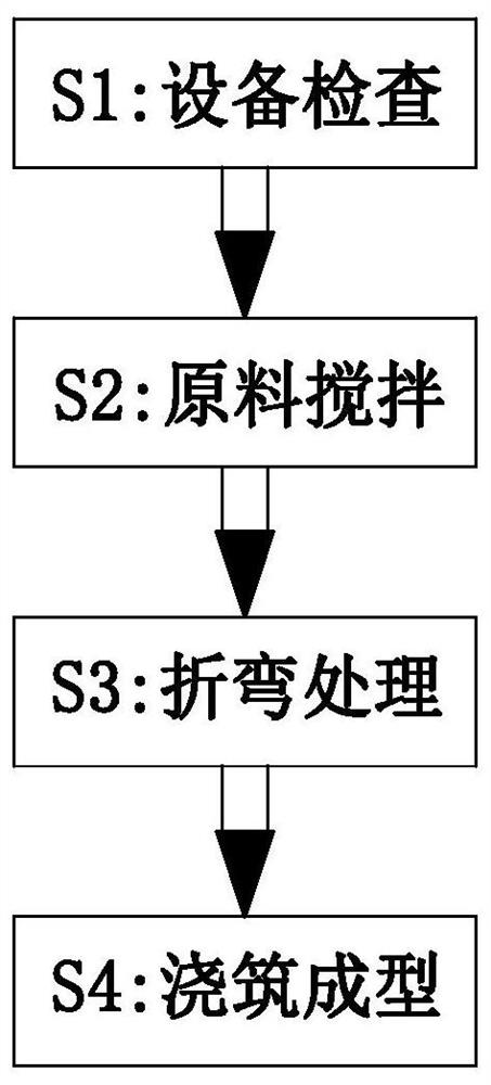
Forming and manufacturing method of building assembly type composite floor
A technology of superimposed floor slabs and manufacturing methods, which is applied to floors, buildings, building components, etc., can solve the problems of increasing the labor intensity of bending workers, reducing bending efficiency, and low bending efficiency, so as to shorten the bending time consumption , Improve the bending effect and high bending efficiency
- Summary
- Abstract
- Description
- Claims
- Application Information
AI Technical Summary
Problems solved by technology
Method used
Image

Examples
Embodiment Construction
[0045] Embodiments of the present invention will be described below with reference to the drawings. In the process, in order to ensure the clarity and convenience of illustration, we may exaggerate the width of the lines or the size of the constituent elements in the diagram.
[0046] In addition, the following terms are defined based on the functions in the present invention, and may be different according to the user's or operator's intention or practice. Therefore, these terms are defined based on the entire content of this specification.
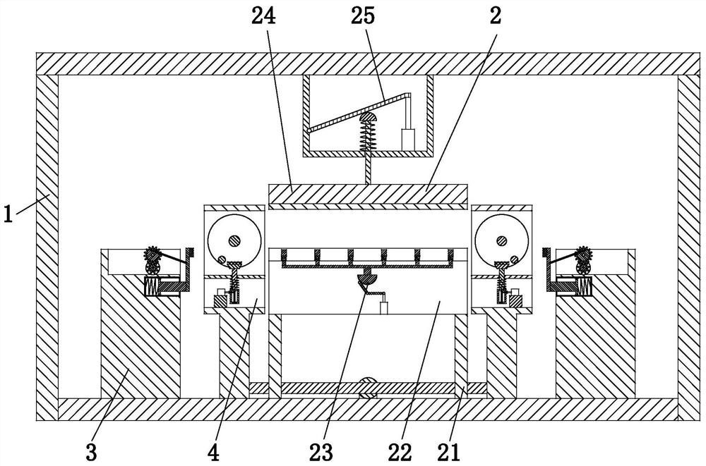
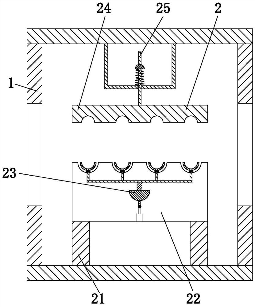
[0047] Such as Figure 1 to Figure 13 As shown, a method for forming a building-assembled laminated floor, which uses a building-assembled laminated floor forming equipment, the building-assembled laminated floor forming equipment includes a frame body 1, a supporting device 2, an alignment The device 3 and the bending device 4 use the above-mentioned building-fabricated laminated floor forming equipment to process the building-fabrica...
PUM
 Abstract
Description
Claims
Application Information