
Eight-chamber RTO organic waste gas treatment device and using method thereof

A technology of organic waste gas and treatment device, applied in the field of eight-chamber RTO organic waste gas treatment device, can solve the problem of limited efficiency improvement, and achieve the effects of good effect, good heat storage effect and high purification efficiency

Pending Publication Date: 2021-03-26
苏州煜鑫环保设备有限公司
View PDF0 Cites 0 Cited by
  • Summary
  • Abstract
  • Description
  • Claims
  • Application Information

AI Technical Summary

Problems solved by technology

Existing RTO equipment is usually two-chamber and three-chamber, but according to the needs of customers, five-chamber and seven-chamber can also be customized. The purpose of increasing the number of regenerators is to improve the efficiency of exhaust gas purification treatment. The RTO equipment can be regarded as an improved version of the three-chamber RTO equipment, and the efficiency is limited compared with the three-chamber RTO equipment. Therefore, the present invention improves on the basis of the second one, increasing the number of regenerators of the RTO equipment to eight, and proposes a An eight-chamber RTO organic waste gas treatment device and its application method

Method used


Image

  • Eight-chamber RTO organic waste gas treatment device and using method thereof
  • Eight-chamber RTO organic waste gas treatment device and using method thereof
  • Eight-chamber RTO organic waste gas treatment device and using method thereof

Examples


Embodiment Construction

[0023] The technical solutions in the embodiments of the present invention will be clearly and completely described below in conjunction with the accompanying drawings provided by the embodiments of the present invention. Obviously, the described embodiments are only preferred embodiments of the present invention, not all implementations. example. Based on the preferred embodiments of the present invention, all other embodiments obtained by persons of ordinary skill in the art without making creative efforts belong to the protection scope of the present invention. The present invention will be described in further detail below.

[0024] In the description of the present invention, it should be understood that the orientations or positional relationships indicated by the terms "upper", "lower", "top", "bottom", "inner" and "outer" are based on those shown in the accompanying drawings. Orientation or positional relationship. The foregoing definitions are only for the convenien...


PUM


Abstract

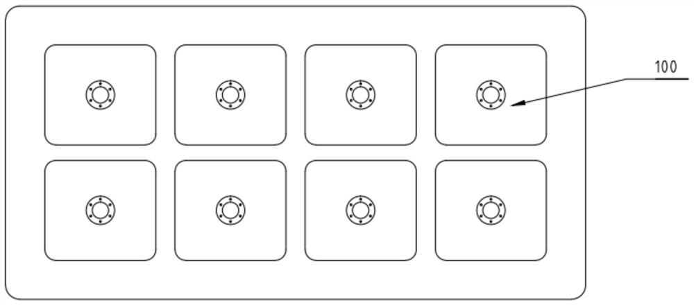
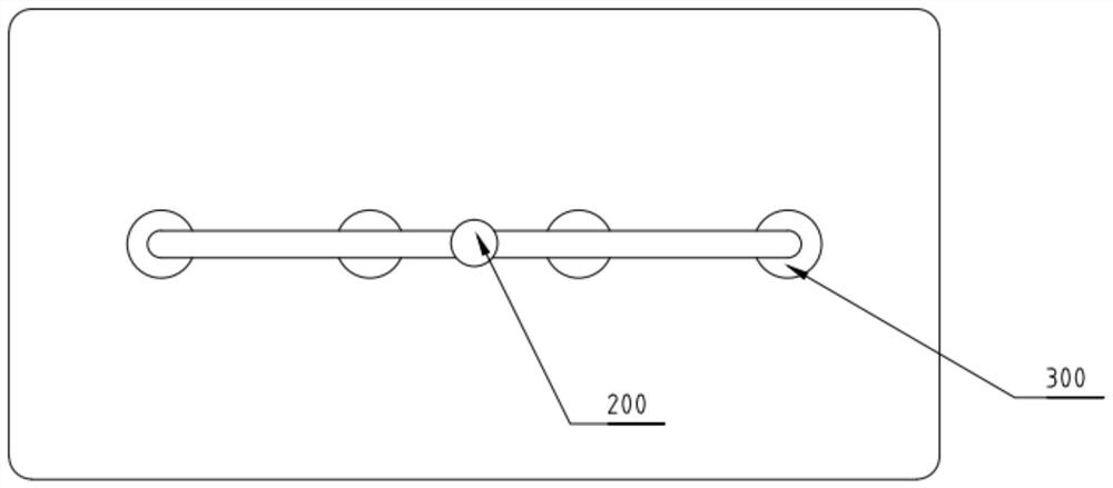
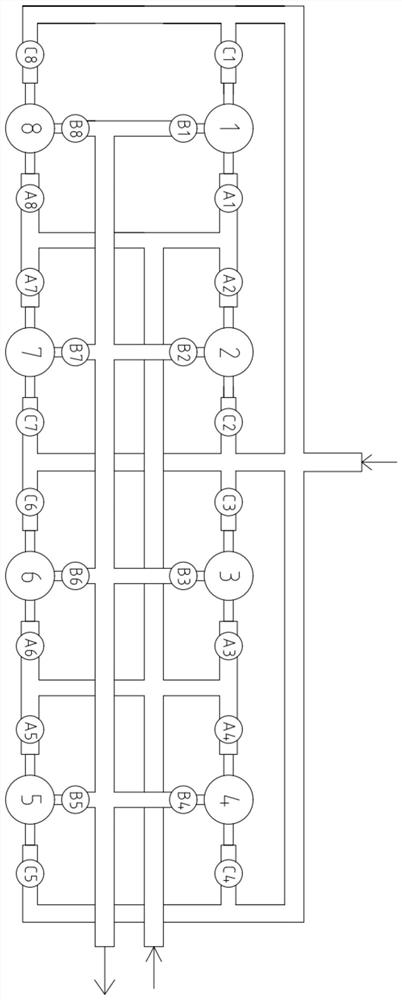
The invention discloses an eight-chamber RTO organic waste gas treatment device which comprises eight regenerative chambers, and the eight regenerative chambers are distributed and aligned in two rowsand four columns and include the first regenerative chamber, the second regenerative chamber, the third regenerative chamber, the fourth regenerative chamber, the fifth regenerative chamber, the sixth regenerative chamber, the seventh regenerative chamber and the eighth regenerative chamber. The upper portions of the eight regenerative chambers are connected with a combustion chamber at the sametime, the combustion chamber is provided with four auxiliary combustion devices, ceramic fiber and refractory bricks are arranged in the regenerative chambers, the bottoms of the regenerative chambersare connected with a four-way connecting pipe, and the four-way connecting pipe communicates with inner cavities of the regenerative chambers, an air inlet pipe, an air outlet pipe and a cleaning pipe correspondingly. An air inlet valve is arranged between the four-way connecting pipe and the air inlet pipe, an air outlet valve is arranged between the four-way connecting pipe and the air outlet pipe, and a cleaning valve is arranged between the four-way connecting pipe and the cleaning pipe. Regular alternate operation is carried out through the eight regenerative chambers so that the treatment efficiency of organic waste gas can be effectively improved, and the service life of equipment is prolonged.

Description

technical field [0001] The invention particularly relates to an eight-chamber RTO organic waste gas treatment device and its usage method. Background technique [0002] Current technical situation: RTO is regenerative thermal incinerator, which is a kind of efficient organic waste gas treatment equipment. The principle is to oxidize the organic matter in the waste gas into corresponding carbon dioxide and water at high temperature, thereby purifying the waste gas, and recovering the heat released when the waste gas is decomposed, so that the heat recovery efficiency reaches more than 95%. The existing RTO equipment is usually two-chamber and three-chamber, but according to the needs of customers, five-chamber and seven-chamber can also be customized. The purpose of increasing the number of regenerators is to improve the efficiency of exhaust gas purification treatment. The RTO equipment can be regarded as an improved version of the three-chamber RTO equipment, and the effic...

Claims


Application Information

Patent Timeline
IPC IPC(8): F23G7/06F23G5/16F23G5/46F23J3/00F23J15/02
CPCF23G5/16F23G5/46F23G7/066F23G2206/10F23J3/00F23J15/025
Inventor 孙大录
Owner 苏州煜鑫环保设备有限公司
Learn More