Photoelectric response measurement method of a photodetector

A photoelectric detector and photoelectric response technology, applied in the direction of measuring devices, optical instrument testing, instruments, etc., can solve the problems of limited measurement methods and inability to achieve high-precision measurement, so as to eliminate uneven response, realize high-precision measurement, The effect of improving dynamic range and signal-to-noise ratio

Active Publication Date: 2021-12-28
UNIV OF ELECTRONICS SCI & TECH OF CHINA
View PDF0 Cites 0 Cited by
  • Summary
  • Abstract
  • Description
  • Claims
  • Application Information

AI Technical Summary

Problems solved by technology

Recently, we also proposed a low-speed optical sampling method (M.K.Wang, S.J.Zhang, Y.T.He, Z.Liu, X.Y.Zhang, H.Wang, Y.X.Ma, B.Sun, Y.L.Zhang, Z.Y.Zhang, and Y.Liu, "Self-referenced frequency response measurement of high-speed photodetectors through segmental up-conversion based on low-speed photonicsampling," Opt.Express 2019, 27(26), 38250-38258), further expanded the measurement frequency on the basis of self-calibration range, so that the measurement frequency range is 2M times the operating frequency range of the microwave signal source, but this method can only measure the photoelectric response at the comb frequency of the optical frequency comb, and cannot achieve arbitrary, flexible and high-precision measurement, and the measurement method is limited

Method used


Image

  • Photoelectric response measurement method of a photodetector
  • Photoelectric response measurement method of a photodetector
  • Photoelectric response measurement method of a photodetector

Examples


Embodiment 1

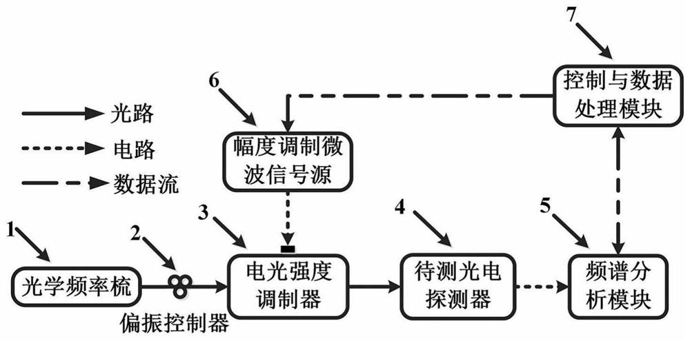
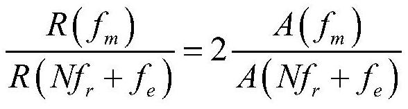
[0061] This embodiment measures the photodetector to be tested at a frequency of 9.94GHz (f m ) relative to a fixed frequency of 100kHz (f e ) of the photoelectric response, the repetition frequency f of the optical frequency comb r is 9.954GHz, then the measurement frequency range is segmented according to the repetition frequency, so that 9.94GHz (f m ) satisfies: 0×f r m r , where N=0.

[0062] Use the control and data processing module to set the center frequency f of the amplitude modulation microwave signal source to 4.97005 GHz, satisfying the following relationship: f m =0×f r +2f-f e , namely f=(f m + f e ) / 2, where the amplitude modulation frequency of the amplitude modulation microwave signal source is also 100kHZ (f e ), using the spectrum analysis module to measure the frequency is 9.94GHz (f m ) and 100kHz (f e ) power, recorded as P(9.94GHz)=-60.60dBm and P(100kHz)=-52.82dBm respectively, then according to formula (6) can be calculated to get R(9.94GHz...

Embodiment 2

[0064] This embodiment measures the photodetector to be tested at a frequency of 9.954GHz (f m ) relative to a fixed frequency of 100kHz (f e ) of the photoelectric response, the repetition frequency f of the optical frequency comb r is 9.954GHz, then the measurement frequency range is segmented according to the repetition frequency, so that 9.954GHz (f m ) satisfies: f m =1×f r , where N=1, take R(f r )≈R(f r + f e ), namely R(f m )≈R(f r + f e ).

[0065] Utilize the control and data processing module to set the center frequency of the amplitude modulation microwave signal source as 2.488GHz (f'=f r / 4-0.0005GHz, Δf=0.0005GHz), the amplitude modulation frequency of the fixed amplitude modulation microwave signal source is 100kHZ (f e ), such that nf r +2f'-f e ≈(n+1)f r -2f'+f e , where n=0~N-1, that is, n=0, then the frequency measured by the spectrum analysis module is 9.9541GHz (f r + f e ), 100kHz (f e ), 4.9759GHz (2f’-f e ) and 4.9781GHz (f r -2f'+f...

Embodiment 3

[0066] Embodiment Three This embodiment measures the photodetector to be tested at a frequency of 29.85GHz (f m ) relative to a fixed frequency of 100kHz (f e ) of the photoelectric response, the repetition frequency f of the optical frequency comb r is 9.954GHz, then the measurement frequency range is segmented according to the repetition frequency, so that 29.85GHz (f m ) satisfies: 2×f r m r , where N=2.

[0067] Use the control and data processing module to set the center frequency f of the amplitude modulation microwave signal source to 4.97105 GHz, satisfying the following relationship: f m =2×f r +2f-f e , namely f=(f m + f e -2f r ) / 2, where the amplitude modulation frequency of the amplitude modulation microwave signal source is also 100kHZ (f e ), using the spectrum analysis module to measure the frequency is 29.85GHz (f m ) and 19.9081GHz (2f r + f e ) are recorded as P(29.85GHz)=-63.09dBm and P(19.9081GHz)=-56.15dBm respectively, then according to formu...


PUM


Abstract

The invention relates to a method for measuring the photoelectric response of a photodetector, which belongs to the field of optoelectronic technology, and aims to provide a wide-band, high-precision, self-calibration method for measuring the photoelectric response of a photodetector. The present invention utilizes the repetition frequency of the optical frequency comb to segment the measuring frequency range of the photodetector to be tested, and within the segment, through the amplitude modulation loaded on the electro-optic intensity modulator, analyze specific frequency components and remove the influence of the electro-optic intensity modulator , to obtain the photoelectric response of the photodetector to be tested in each segment, then set the output frequency of the amplitude modulation microwave signal source, perform inter-segment splicing and eliminate the influence of the optical frequency comb, and finally obtain the wide-band photoelectric response of the photodetector to be tested. Response, wherein, by changing the output frequency of the amplitude modulation microwave signal source, the photoelectric response measurement of the photodetector under test at any frequency within a wide frequency band can be realized.

Description

technical field [0001] The invention belongs to the photoelectric response measurement technology of a photodetector in the field of optoelectronic technology, and in particular relates to a photoelectric response measurement method of a photodetector. Background technique [0002] Photodetectors convert optical modulation signals into electrical signals, so that high-resolution analysis of optical signals can be performed in the electrical domain. They are key devices in microwave photonic systems, and their photoelectric responses directly affect the working speed and performance of the entire system. With the increasingly wide bandwidth and high resolution requirements of the system, the measurement of the photoelectric response of photodetectors in a wide frequency band poses a huge challenge, especially for high-resolution applications in an ultra-wide frequency range, so it is urgent to develop A wide-band, high-precision photoelectric response measurement method for p...

Claims


Application Information

Patent Timeline
Patent Type & Authority Patents(China)
IPC IPC(8): G01D18/00G01M11/00
CPCG01D18/00G01M11/00
Inventor 张尚剑王梦珂徐映何禹彤刘永
Owner UNIV OF ELECTRONICS SCI & TECH OF CHINA
Why Eureka
Try Eureka