
Electric appliance element sealing structure and clothes treatment device applying same

A technology for clothes processing devices and electrical components, which is applied in the direction of electrical components, applications, washing devices, etc., which can solve the problems of inability to achieve airtightness, unclear glue sizing path and dosage at seams, and easy detachment, so as to increase the capacity of electrical appliances The space of components, ensuring the consistency and stability of mass production, and the effect of increasing the bonding area

Active Publication Date: 2021-03-26
QINGDAO HAIER WASHING MASCH CO LTD +1
View PDF4 Cites 0 Cited by
  • Summary
  • Abstract
  • Description
  • Claims
  • Application Information

AI Technical Summary

Problems solved by technology

[0005] A. Use a sealed cover to cover the electrical components and circuits, and lead the wires out from the lower part of the sealed cavity. Although the sealed cavity is realized in the structure of Scheme A, it cannot be sealed and cannot prevent water vapor from entering. For example, when the washing machine is at high temperature When used in a humid environment, water vapor may condense and cause short circuits and other failures in the terminals of the control circuit or electrical components
[0006] B. Use the sealing cover to cover the electrical components and the circuit, press the sealing strip or gasket at the seam for sealing, wrap the wire at the outlet with rubber plug or foam and lead it out. In plan B, the sealing strip or gasket is It is easy to fall out during the actual installation process, resulting in failure and poor durability; in addition, the sealing strip can only be attached manually, which is inefficient and difficult to mass produce; and the outlet cannot prevent water vapor or water droplets from entering, and there is still a risk of water vapor condensation
[0007] C. Use a sealing cover to cover the electrical components and circuits, use glue to seal the seams, and apply glue to seal the outlets; in plan C, the glue application path and dosage at the seams are not clear, and there are quality risks. After the outlet is coated with glue, it is difficult to ensure that the gap between the wires is completely sealed, and there is still a risk of water vapor entering

Method used


Image

  • Electric appliance element sealing structure and clothes treatment device applying same
  • Electric appliance element sealing structure and clothes treatment device applying same
  • Electric appliance element sealing structure and clothes treatment device applying same

Examples


Embodiment 1

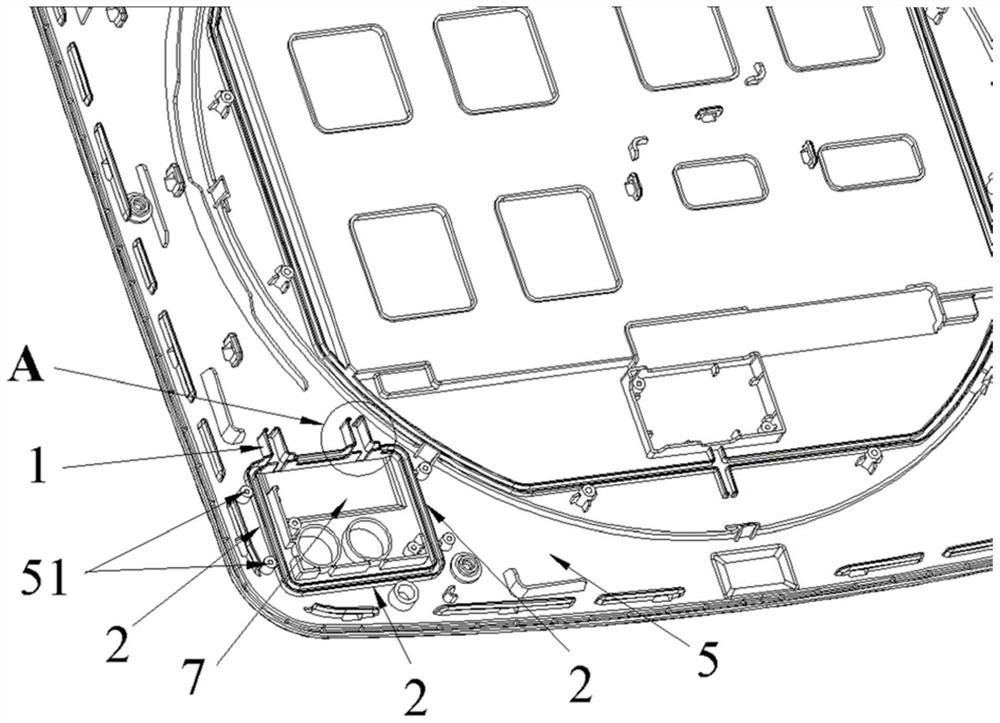
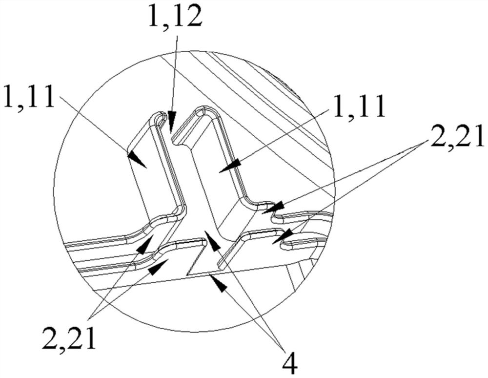
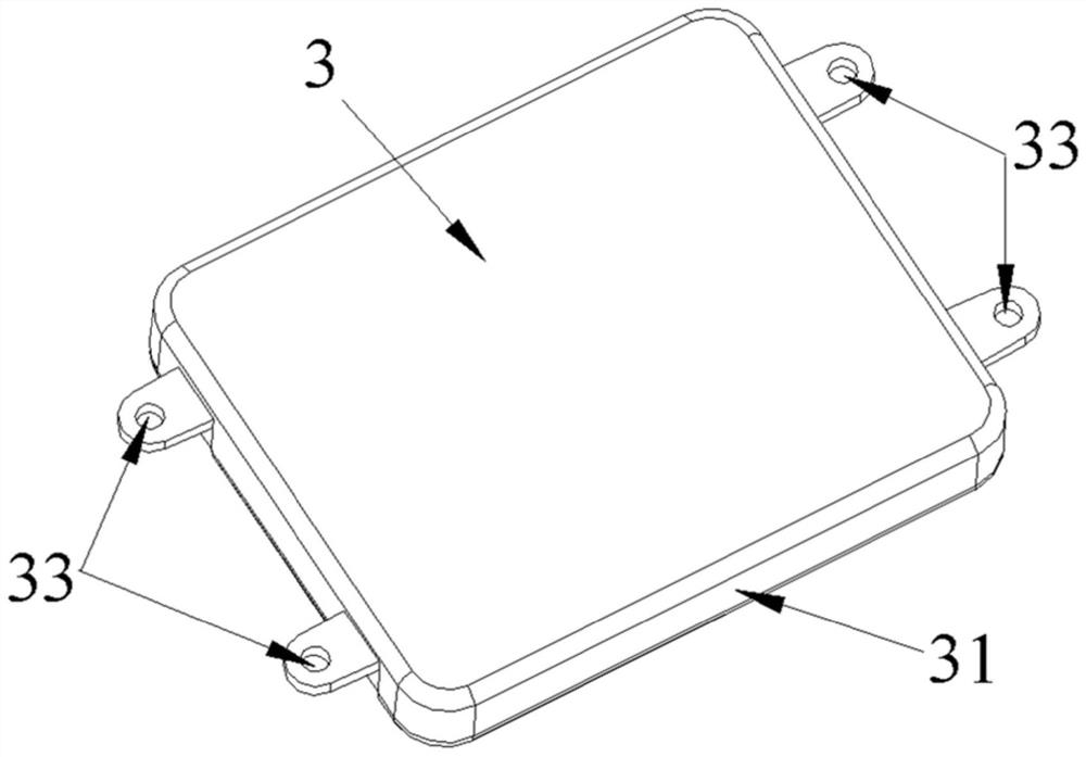
[0051] In this example, if figure 1 As shown, a sealing structure for electrical components is provided, including: an installation body 5, which is provided with a glue filling groove 2 surrounding the electrical components; a sealing cover 3, which is sealed and buckled with the glue filling groove 2; the glue filling groove One side of 2 extends outwards and is provided with a wire passing groove 1 communicating with the glue filling groove 2, and the wire passing groove 1 is used for passing the wires 6 of electrical components.

[0052] In this embodiment, potting glue is often used for bonding, sealing and coating protection of electronic components. The potting glue used is in a liquid state before it is cured and has a certain fluidity. After it is completely cured, it can play a role Waterproof, dustproof, insulation, heat conduction, sealing, anticorrosion, heat resistance, shockproof and other functions. In the present invention, in order to make the potting glue p...

Embodiment 2

[0070] The difference between this embodiment and embodiment 1 is:

[0071] In this embodiment, the extension end of the wire passing groove 1 is clamped with the wire 6 of the electrical component, and the intersection of the wire passing groove 1 and the glue filling tank 2 is provided with a clamping connection with the wire 6 of the electrical component. Snap-in structure (not shown in the attached drawings).

[0072] In this embodiment, due to the long length of the wire trough, in order to ensure that the wires in the middle will not bulge due to bending, a structure for clamping the wires can be provided at the position where the glue potting groove communicates with the wire trough, for example, a wire clip The claws located at the bottom of the wire trough.

[0073] In this embodiment, in the specific processing process, in order to achieve a better glue filling effect, the width of the glue filling groove can be widened near the wire groove (due to the widening of t...

Embodiment 3

[0078] In this embodiment, a clothes processing device is provided, the clothes processing device adopts an operation interface including touch buttons and a touch screen, and the control panel has a built-in computer board for the touch screen and touch buttons with relatively complicated wiring and the button element, the clothes treatment device uses the sealing structure as described in Embodiment 1 or 2 to seal the button element arranged on the installation main body 5 . The clothes processing device is selected from one of a washing machine, a clothes dryer, and an integrated washing and drying machine.


PUM


Abstract

The invention discloses an electric appliance element sealing structure and a clothes processing device using the same, the sealing structure comprises a mounting main body provided with a glue pouring groove surrounding an electric appliance element, and a sealing cover buckled with the glue pouring groove in a sealing manner; and one side of the glue pouring groove extends outwards to be provided with a wire passing groove communicated with the glue pouring groove, and the wire passing groove is used for allowing a wire of an electric appliance element to penetrate through. The electric appliance element sealing structure provided by the invention is provided with the wire passing groove structure special for electric control elements such as a button, so that an accurate gluing route isprovided, the consistency and stability of mass production are ensured, the sealing effect on the mounting main body and the electric appliance element is further improved, particularly, the sealingeffect on a wire is improved, and the electric appliance element sealing structure is suitable for popularization and application.

Description

technical field [0001] The invention belongs to the technical field of household appliances, and in particular relates to a sealing structure of electrical components and a clothes treatment device using the same. Background technique [0002] With the popularization of Internet of Things technology in home appliances, consumers are becoming more and more accustomed to using operation interfaces that can be operated by touch and other methods to control appliances. However, the printed control interface and digital tube display used in traditional electrical appliances can no longer meet the needs of consumers in terms of aesthetics and practicality. They have been replaced by touch screen displays with better human-computer interaction performance. [0003] However, due to the relatively complex control circuits of touch screens and touch buttons, there are many requirements for the structure of the control interface and electrical appliances, especially for the waterproof ...

Claims


Application Information

Patent Timeline
Patent Type & Authority Applications(China)
IPC IPC(8): H05K5/06H05K5/00D06F34/28
CPCH05K5/0017H05K5/069H05K5/064D06F39/00
Inventor 姜永富刘尊安张开宏李峰杨乐吴建新
Owner QINGDAO HAIER WASHING MASCH CO LTD
Learn More