Supercharge Your Innovation With Domain-Expert AI Agents!

Composite material beam joint

A composite material, together technology, applied in the direction of chords/stringers, wings, aircraft parts, etc., can solve the problems of difficult composite materials, lower connection efficiency, lower connection height, etc., to improve connection efficiency, increase application methods, The effect of increasing the connection height

Inactive Publication Date: 2021-03-30
CHENGDU AIRCRAFT DESIGN INST OF AVIATION IND CORP OF CHINA
View PDF7 Cites 0 Cited by
  • Summary
  • Abstract
  • Description
  • Claims
  • Application Information

AI Technical Summary

Problems solved by technology

[0002] Although composite materials are widely used in aircraft structures, the aircraft wing structure with a beam layout needs to be connected to the fuselage through the joint lugs on the beams, which limits the application of all-composite materials on the load-carrying beams. An important The reason is that the joints on composite beams are not easy to design
From the perspective of connection efficiency, it is better to set the connecting lugs of the wing body on the beam flange or to increase the distance between the connecting bolts of the wing body as much as possible. It is easy to deal with metal beams, but it is very difficult for composite materials, so the connecting holes are generally set On beam webs without dedicated connection lugs
Because the mechanical connection holes of composite materials require larger side distances, the connection height is greatly reduced, the nail load is increased, and the connection efficiency is greatly reduced. Larger bolt diameters and thicker connection lugs are required, which seriously restricts the use of composite materials Application on main load-carrying beams

Method used


Image

  • Composite material beam joint
  • Composite material beam joint
  • Composite material beam joint

Examples


Embodiment Construction

[0011] The present invention will be further described in detail below in conjunction with specific embodiments with reference to the accompanying drawings.

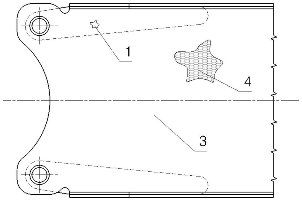
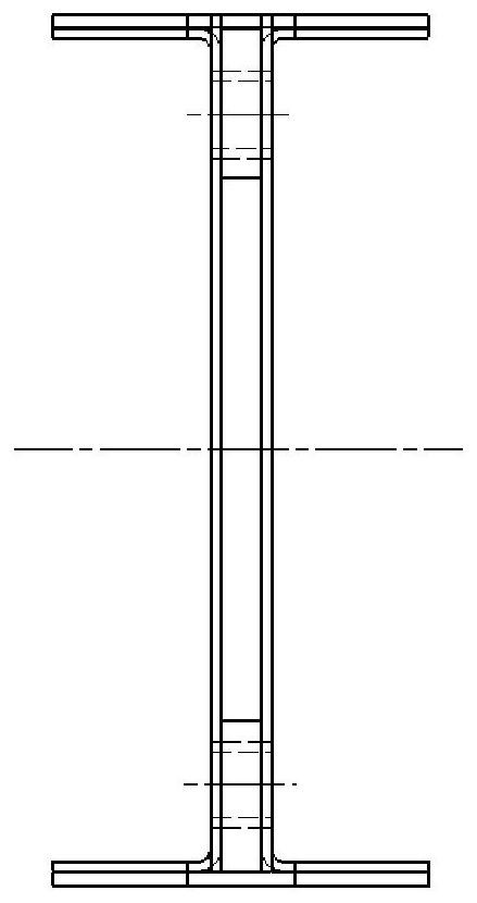
[0012] Figure 1-3 Respectively a front view, a side view and a top view of the composite beam joint of the present invention; Figure 4 Schematic diagram of the structure of the load transfer link.

[0013] As shown in the figure, the composite beam joint of the present invention includes a beam flange 2 and a beam web 3, wherein the interlayer of the beam web 3 includes a spliced ​​sandwich core 4 and a load transfer link 1, which together serve as the beam web 3 The middle interlayer, the load transmission link 1 is arranged along the longitudinal direction of the beam. The load transfer link 1 comprises a link 5, an intermediate piece 6 and a bushing 7 (see Figure 4 ), wherein the link 5 is sleeved on the bushing 7, and the intermediate piece 6 fills the remaining space in the link 5, and the bushing 7 is equal i...


PUM


Abstract

The invention discloses a composite material beam joint. The composite material beam joint comprises a beam flange (2) and a beam web (3), wherein the beam web (3) comprising a sandwich (4) and a loadtransmission link (1) together as an intermediate sandwich of the beam web (3), the load transmission link (1) being arranged in the longitudinal direction of the beam, the load transmission link (1)comprising a link (5), an intermediate piece (6) and a bushing (7), and the chain link (5) being sheathed on the bushing (7), the middle piece (6) fills the remaining space in the chain ring (5), andthe lining (7) and a connecting hole in a panel of the beam web (3) are equal in size and coaxial. According to the composite material beam joint, the load transmission chain ring is added in the composite material beam to reduce the edge distance and the end distance of the connecting lugs of the beam joint, so the connecting height is increased, connecting efficiency is improved, the weight isreduced, and the application mode of the composite material beam is increased.

Description

technical field [0001] The invention belongs to the technical field of composite material structure design, and in particular relates to a composite material beam joint. Background technique [0002] Although composite materials are widely used in aircraft structures, the aircraft wing structure with a beam layout needs to be connected to the fuselage through the joint lugs on the beams, which limits the application of all-composite materials on the load-carrying beams. An important The reason is that the joints on composite beams are not easy to design. From the perspective of connection efficiency, it is better to set the connecting lugs of the wing body on the beam flange or to increase the distance between the connecting bolts of the wing body as much as possible. It is easy to deal with metal beams, but it is very difficult for composite materials, so the connecting holes are generally set There are no special connection lugs on the beam web. Because the mechanical co...

Claims


Application Information

Patent Timeline
IPC IPC(8): B64C3/18B64C1/26
CPCB64C3/182B64C1/26B64C2001/0072
Inventor 陈建农刘衍腾梁兵张庆茂刘伟先彭涛
Owner CHENGDU AIRCRAFT DESIGN INST OF AVIATION IND CORP OF CHINA
Features
  • R&D
  • Intellectual Property
  • Life Sciences
  • Materials
  • Tech Scout
  • Unparalleled Data Quality
  • Higher Quality Content
  • 60% Fewer Hallucinations
Learn More