

Construction method of flexible vertical anti-seepage wall for blocking underground water pollution
A technology of groundwater pollution and construction method, which is applied in the field of flexible vertical cut-off wall construction, and can solve the problems of HDPE geomembrane laying down, membrane connection and groove formation, etc.
- Summary
- Abstract
- Description
- Claims
- Application Information
AI Technical Summary
Problems solved by technology
Method used
Image

Examples
Embodiment 1
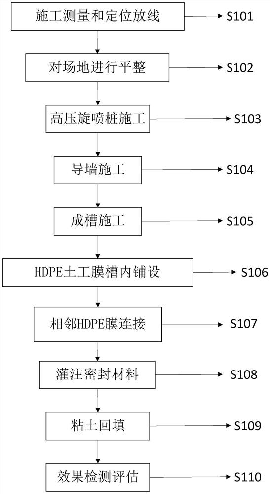
[0060] S101. After hydrological and geological conditions investigation and pollution investigation in the early stage of the site, the designer proposes the anti-seepage path and anti-seepage depth, and the construction party conducts site measurement and setting-out. When there are construction obstacles in the seepage path in space, timely communicate with the supervisor, construction party and designer for changes.
[0061] S102. Clean up and level the construction work surface, remove obstacles within 2 meters below the ground of the construction site, and clean up caves on the foundation soil or tree roots, garbage and other sundries on the surface of the foundation. According to the comparison between the original landform elevation and the design elevation, the construction volume for site leveling is calculated, and the sundries transportation route map and traffic guidance plan are drawn. At the same time, rationally arrange the positions of construction machinery, t...
PUM
| Property | Measurement | Unit |
|---|---|---|
| Width on one side | aaaaa | aaaaa |
| Depth | aaaaa | aaaaa |
Abstract
Description
Claims
Application Information