Water-lubricated thrust pad lateral elastic baffle limit structure

A technology of elastic baffle and limit structure, which is applied to sliding contact bearings, rotating bearings, shafts and bearings, etc., can solve the problem of increasing cost and complexity, locking that does not reach the expected loosening, and multi-process cost control Cost and other issues, to achieve the effect of increasing the preload function, reducing the effectiveness, and reducing the complexity of the system

Active Publication Date: 2022-05-13
HARBIN ELECTRIC POWER EQUIP
View PDF21 Cites 0 Cited by
  • Summary
  • Abstract
  • Description
  • Claims
  • Application Information

AI Technical Summary

Problems solved by technology

Traditional pressurized water reactor nuclear power plants generally adopt the safety concept of addition, that is, increase system redundancy or equipment redundancy. Although the safety is improved, the cost and complexity increase. and integration, reducing system complexity and improving system reliability
Traditional shielded motors or wet winding motors use water-lubricated bearing technology to balance the axial water thrust. The thrust tile uses a baffle to fit the side of the tile base to limit the circumference of the graphite tile surface, but the baffle and the thrust tile base use bolts. The closing position is just located in the flow channel between the two thrust pads, where the bearing flow field is relatively complicated and the flow velocity is high. It is expected to be loose and fall, which will have a certain impact on the safe operation of the motor. In order to control the locking effect, more process costs and complex process control costs are required

Method used


Image

  • Water-lubricated thrust pad lateral elastic baffle limit structure
  • Water-lubricated thrust pad lateral elastic baffle limit structure
  • Water-lubricated thrust pad lateral elastic baffle limit structure

Examples


Embodiment 1

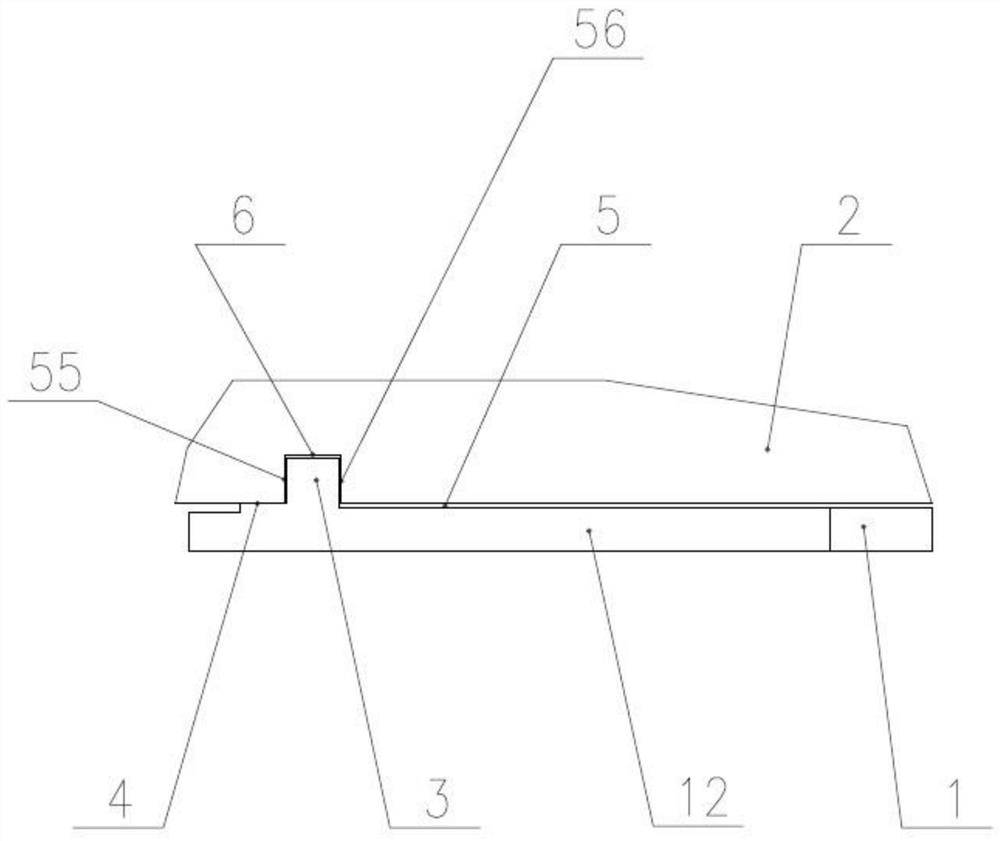
[0025] figure 1 It is a water-lubricated thrust tile lateral elastic baffle limit structure suitable for third-generation nuclear power plants. It is composed of side baffles, tile bases, and tile surfaces. The invention adds a self-locking structure, the side baffle is inserted into the side groove of the thrust tile to lift the lock arm, and the side baffle is inserted into the thrust tile to the position and then the lock arm is lowered, so that the limit head of the lock arm snaps into the thrust tile, And the preload step is set to keep the relative position of the side baffle and the tile base fixed, avoiding the cumbersome structure of the traditional water-lubricated bearing pad using screws to close the side baffle, reducing parts and improving reliability.

[0026] Such as figure 1 As shown, the water-lubricated thrust pad side elastic baffle limit structure, the first side baffle 1 is provided with a lock arm 12, the lock arm 12 is a cantilever beam structure, and ...

Embodiment 2

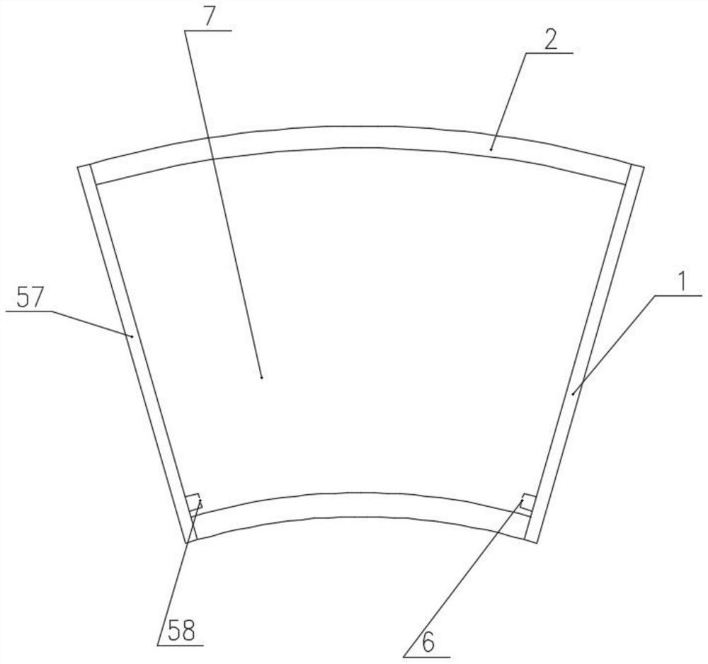
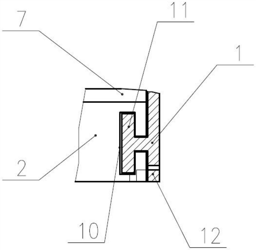
[0033] Such as Figure 7 As shown, a second limit head 15 is provided at the tail of the lock arm 12, and the upper side of the second limit head 15 forms a first contact surface 14 with the thrust shoe 2, and a certain preload ensures that the thrust shoe 2 is in the circumferential direction. There is no relative displacement in the radial direction, there is a sixth gap 17 in the horizontal direction on the left side of the second limiting head 15, there is a seventh gap 16 in the horizontal direction on the right side of the second limiting head 15, and the vertical direction is on the lower left side of the second limiting head 15. There is an eighth gap 18, and there is a ninth gap 19 in the vertical direction on the lower right side of the second limit head 15. By adjusting the height values ​​of the eighth gap 18 and the ninth gap 19, the height of the lock arm 12 of the cantilever beam structure can be adjusted. The preload and the amount of deformation ensure that th...

Embodiment 3

[0035] Such as Figure 8 As shown, a third limit head 24 is provided at the tail of the lock arm 12, and there is a tenth gap 21 between the upper left side of the third limit head 24 and the thrust shoe 2, and the upper right side of the third limit head 24 forms a third gap 21 with the thrust shoe 2. The second contact surface 20, through a certain preload, ensures that there is no relative displacement with the thrust pad 2 in the circumferential and radial directions. There is an eleventh gap 22 in the horizontal direction on the left side of the third limit head 24. The third limit head 24 There is a twelfth gap 23 in the horizontal direction on the right side, there is a thirteenth gap 25 in the vertical direction on the lower left side of the third limiting head 24, and there is a fourteenth gap 26 in the vertical direction on the lower right side of the third limiting head 24. The height values ​​of the thirteenth gap 25 and the fourteenth gap 26 are used to adjust the...


PUM


Abstract

The invention relates to a water-lubricated thrust shoe lateral elastic baffle limit structure, the first side baffle (1) is provided with a lock arm (12), the lock arm (12) is provided with a first limit head (3), the first The limit head (3) is inserted into the thrust tile base (2), and there is a first gap (55) in the left vertical direction between the first limit head (3) and the thrust tile base (2). The invention adds a self-locking structure, the side baffle is inserted into the side groove of the thrust tile to lift the lock arm, and the side baffle is inserted into the thrust tile to the position and then the lock arm is lowered, so that the limit head of the lock arm snaps into the thrust tile, And the preload step is set to keep the relative position of the side baffle and the tile base fixed, avoiding the cumbersome structure of the traditional water-lubricated bearing pad using screws to close the side baffle, reducing parts and improving reliability. The invention is suitable for the water-lubricated thrust bearing of the shielded motor of the high-power nuclear main pump of the third-generation nuclear power, and can be widely used in the fields of nuclear power, national defense, chemical industry, ship power and the like.

Description

technical field [0001] The invention relates to a lateral elastic baffle limiting structure of a water-lubricated thrust pad, which is applied to the field of nuclear reactor coolant pump water-lubricated bearings. Background technique [0002] Improving the reliability of the reactor coolant pump (referred to as the nuclear main pump) is of great significance to improving the safety level of nuclear power plants. Traditional pressurized water reactor nuclear power plants generally adopt the safety concept of addition, that is, increase system redundancy or equipment redundancy. Although the safety is improved, the cost and complexity increase. and integration, reducing system complexity and improving system reliability. Traditional shielded motors or wet winding motors use water-lubricated bearing technology to balance the axial water thrust. The thrust tile uses a baffle to fit the side of the tile base to limit the circumference of the graphite tile surface, but the baff...

Claims


Application Information

Patent Timeline
Patent Type & Authority Patents(China)
IPC IPC(8): F16C17/04F16C33/10
CPCF16C17/04F16C33/1025
Inventor 王伟光索文旭吕向平付嵩李洋张金慧
Owner HARBIN ELECTRIC POWER EQUIP
Why Eureka
Try Eureka