
Fire safety protection system for oil pipeline

A technology for safety protection and pipelines, applied in pipeline systems, mechanical equipment, gas/liquid distribution and storage, etc., can solve problems such as oil pipeline damage, personnel injury, fire, explosion accidents, etc.

Pending Publication Date: 2021-03-30
DALIAN FUJIA DAHUA GASOLINEEUM CHEM
View PDF0 Cites 0 Cited by
  • Summary
  • Abstract
  • Description
  • Claims
  • Application Information

AI Technical Summary

Problems solved by technology

The pipeline may be damaged due to factors such as improper operation and external force collisions, resulting in damage to the oil pipeline and leakage. After a large amount of oil leakage, it will cause environmental protection accidents; when the oil leakage reaches a certain amount, the concentration of oil and gas reaches the explosion limit. In case of open flame or static electricity, fire and explosion accidents will occur, resulting in secondary accidents, which will cause personal injury and damage to equipment and facilities, and bring serious economic losses to the enterprise

Method used


Image

  • Fire safety protection system for oil pipeline
  • Fire safety protection system for oil pipeline

Examples


Embodiment 1

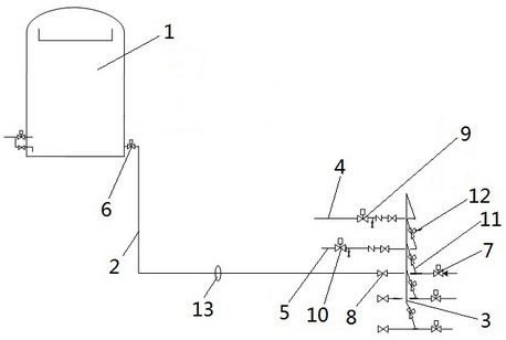
[0021] Such as figure 1 As shown, the oil pipeline fire safety protection system includes: receiving tank 1, oil pipeline 2, collection pipeline 3, nitrogen pipeline 4, fire pipeline 5; receiving tank 1, used for storing oil, oil pipeline 2 is connected to the receiving tank 1, and the oil pipeline 2 is provided with the root valve 6 of the receiving tank, the primary valve 8 of the boundary area, and the secondary valve 7 of the boundary area in sequence. The root valve 6 of the receiving tank is close to the bottom of the receiving tank 1, and the The primary valve 8 of the zone and the secondary valve 7 of the zone are close to the boundary of the pipeline.

[0022] The collection pipeline 3 is set at the boundaries of each pipeline, the collection pipeline 3 is connected to the oil pipeline 2 through the connecting pipeline 11, and the connection point between the connecting pipeline 11 and the oil pipeline 2 is located between the primary valve 8 in the boundary zone and ...

Embodiment 2

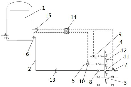
[0029] Such as figure 2 As shown, the present embodiment also includes a control device 14, a liquid level detection device 15, and an alarm device on the basis of Embodiment 1; the liquid level detection device 15 is located on the receiving tank 1 and is connected with the control device 14 for automatic detection The liquid level of the oil in the receiving tank 1.

[0030] The alarm device is located on the oil pipeline 2 and is connected with the control device 14, and is used for automatically sending out an alarm signal when the oil pipeline 2 leaks.

[0031] The control device 14 has the function of automatic remote control, which is used to receive the alarm signal sent by the alarm device, and issue instructions according to the alarm signal to control the opening or closing of the solenoid valves on the oil pipeline 2 and nitrogen pipeline 4; at the same time, it receives liquid level detection The signal sent by the device 15, and an instruction is issued accordi...


PUM


Abstract

The invention relates to a fire safety protection system for an oil pipeline. The fire safety protection system comprises a receiving tank, the oil pipeline, a nitrogen pipeline and a fire pipeline, the oil pipeline is connected with the receiving tank, a receiving tank root valve and a boundary area secondary valve are arranged on the oil pipeline, the nitrogen pipeline is connected with the oilpipeline, a nitrogen supply valve is arranged on the nitrogen pipeline, the fire pipeline is connected with the oil pipeline, and a fire-fighting water supply valve is arranged on the fire pipeline. The nitrogen pipeline and the fire pipeline are connected to the oil pipeline, so that effective fire-fighting treatment can be performed on leakage points on the oil pipeline, and harm caused by oil product leakage is reduced.

Description

technical field [0001] The invention relates to the field of chemical technology, in particular to an oil pipeline fire safety protection system. Background technique [0002] During the chemical production process, the materials produced by the device are transported through pipelines to the storage tanks of the corresponding products in the tank farm for storage. The pipeline may be damaged due to factors such as improper operation and external force collisions, resulting in damage to the oil pipeline and leakage. After a large amount of oil leakage, it will cause environmental protection accidents; when the oil leakage reaches a certain amount, the concentration of oil and gas reaches the explosion limit. In case of open flame or static electricity, fire and explosion accidents will occur, resulting in secondary accidents, which will cause personal injury and damage to equipment and facilities, and bring serious economic losses to the enterprise. Contents of the inventi...

Claims


Application Information

Patent Timeline
Patent Type & Authority Applications(China)
IPC IPC(8): F17D1/02F17D1/08F17D3/01F17D5/02F17D5/06
CPCF17D1/02F17D1/086F17D3/01F17D5/02F17D5/06
Inventor 郝毅李辉李德武冯志涛
Owner DALIAN FUJIA DAHUA GASOLINEEUM CHEM
Learn More