Electric pile heating device and fuel cell system hierarchical control method

A heating device and stack technology, which is applied to fuel cells, circuits, electrical components, etc., can solve the problems of slow heating speed of stacks and large heating consumption at startup.

Active Publication Date: 2021-03-30
DONGFENG MOTOR CORP HUBEI
View PDF10 Cites 4 Cited by
  • Summary
  • Abstract
  • Description
  • Claims
  • Application Information

AI Technical Summary

Problems solved by technology

[0004] One of the purposes of the present application is to provide a stack heating device, which aims to improve the proble...

Method used


Image

  • Electric pile heating device and fuel cell system hierarchical control method
  • Electric pile heating device and fuel cell system hierarchical control method
  • Electric pile heating device and fuel cell system hierarchical control method

Examples


no. 1 example

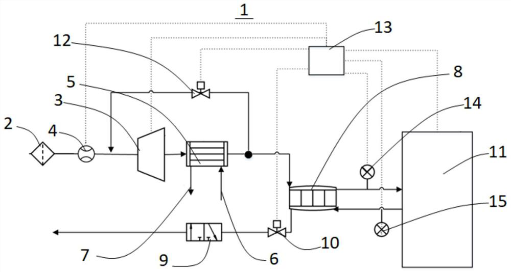
[0061] Please refer to figure 1 , the application provides a stack heating device 1, including an air filter 2, the inlet pipe of the air compressor 3 is connected to the outlet pipe of the air filter 2 through the air flow meter 4, and the inlet pipe of the intercooler 5 is connected to the air The outlet pipe of the compressor 3, and the inlet cooling pipe 6 and the outlet cooling pipe 7 are respectively connected to the intercooler 5; the dry air side inlet of the humidifier 8 is connected to the first outlet pipe of the intercooler 5, and the humidifier The wet air side outlet of 8 is connected to the mixer 9 through the back pressure valve 10; at the same time, the air inlet of the stack 11 is connected to the dry air side outlet of the humidifier 8, and the air outlet is connected to the humid air of the humidifier 8 side inlet; the inlet pipe of the preheating valve 12 is connected to the second outlet pipe of the intercooler 5, and the outlet pipe is connected to the i...

no. 2 example

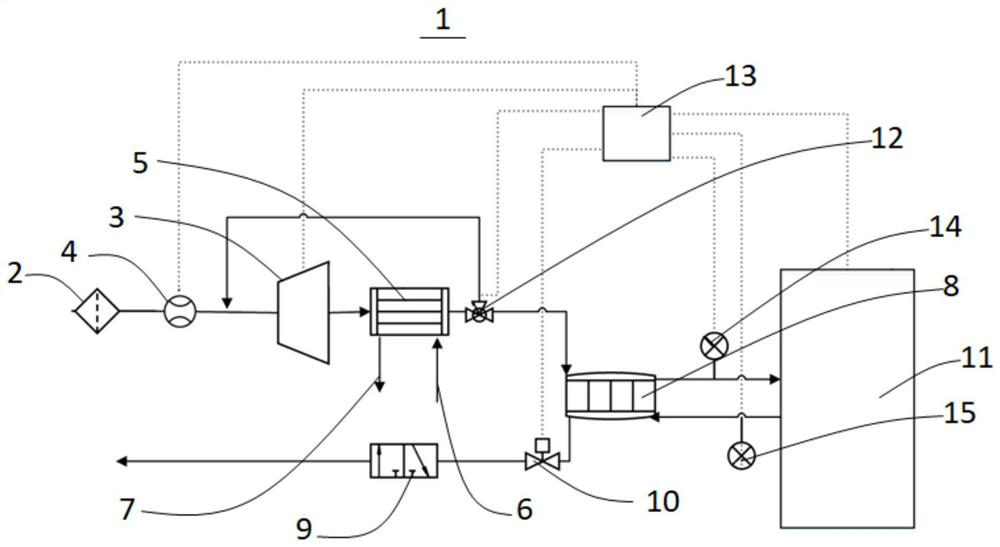
[0080] Please refer to figure 2 , the application provides a stack heating device 1, including an air filter 2; the inlet pipe of the air compressor 3 is connected to the outlet pipe of the air filter 2 through an air flow meter 4; the inlet pipe of the intercooler 5 is connected to The outlet pipe of the air compressor 3, and the inlet cooling pipe 6 and the outlet cooling pipe 7 are respectively connected to the intercooler 5; the inlet pipe of the preheating valve 12 is connected to the outlet pipe of the intercooler 5, and the second outlet pipe is connected to The air inlet pipe of the air compressor 3; the dry air side inlet of the humidifier 8 is connected to the first outlet pipe of the preheating valve 12, and the wet air side outlet of the humidifier 8 is connected to the mixed air through the back pressure valve 10. Discharge device 9; The air inlet of stack 11 is connected to the dry air side outlet of humidifier 8, and the air outlet is connected to the wet air s...

no. 3 example

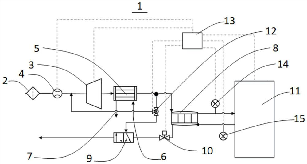
[0098] Please refer to image 3 , the application provides a stack heating device 1, which mainly includes an air filter 2; the air intake inlet pipe of the air compressor 3 is connected to the outlet pipe of the air filter 2 through an air flow meter 4; the inlet pipe of the intercooler 5 Connected to the outlet pipe of the air compressor 3, and the intercooler 5 is respectively connected to the inlet cooling pipe 6 and the outlet cooling pipe 7; the dry air side inlet of the humidifier 8 is connected to the first outlet pipe of the intercooler 5; Preheat valve 12, the inlet pipe of preheat valve 12 is connected to the second outlet pipe of intercooler 5, and the first outlet pipe is connected to the intake inlet pipe of air compressor 3; the humid air side outlet of humidifier 8 It is connected to the mixer 9 through the back pressure valve 10, and the second outlet pipe of the preheating valve 12 is connected to the mixer 9; the air inlet of the stack 11 is connected to the...


PUM


Abstract

The invention provides an electric pile heating device and a fuel cell system hierarchical control method, and belongs to the field of cells. An air inlet pipe of an air compressor is connected to anoutlet pipe of an air filter through an air flow meter. An inlet pipe of the intercooler is connected to an outlet pipe of the air compressor, and the intercooler is connected with an inlet cooling pipe and an outlet cooling pipe. A dry air side inlet of the humidifier is connected to a first outlet pipe of the intercooler; a humid air side outlet of the humidifier is connected to the mixing and discharging device through a back pressure valve; an air inlet of the galvanic pile is connected to a dry air side outlet of the humidifier, and an air outlet of the galvanic pile is connected to a wetair side inlet of the humidifier; an inlet pipe of the preheating valve is connected to a second outlet pipe of the intercooler, and an outlet pipe of the preheating valve is connected to an air inlet pipe of the air compressor. The controller is electrically connected with the air flow meter, the air compressor, the preheating valve, the back pressure valve and the galvanic pile. The device is small in occupied space, and the power consumption of low-temperature cold start of the whole fuel cell system is reduced.

Description

technical field [0001] The present application relates to the field of batteries, in particular to a stack heating device and a hierarchical control method for a fuel cell system. Background technique [0002] The proton exchange membrane fuel cell system includes electric stack, air system, hydrogen system, cooling system and corresponding control system. The start-up of fuel cells under low temperature conditions will be hindered by the freezing of residual water and generated water. Ice will fill the pores of the catalytic layer or diffusion layer, reducing or even stopping the electrochemical reaction, and affecting the low-temperature start-up performance of the stack. At the same time, when water freezes, it will expand in volume, and when the battery is turned on, the heat generated will melt the ice into water, and the volume will decrease again. Repeated phase changes will have a great impact on the structure of battery materials, battery performance and life. . F...

Claims


Application Information

Patent Timeline
IPC IPC(8): H01M8/04225H01M8/04302H01M8/04223H01M8/04029H01M8/04089
CPCH01M8/04029H01M8/04089H01M8/04268H01M8/04225H01M8/04302Y02E60/50
Inventor 马义史建鹏王章张剑张明凯
Owner DONGFENG MOTOR CORP HUBEI
Why Eureka
Try Eureka