Ceramic spark plug forming equipment and control method thereof

A technology for forming equipment and spark plugs, applied in the field of ceramic spark plug forming equipment and its control, can solve problems such as reducing production efficiency, and achieve the effects of improving production efficiency and processing accuracy

Active Publication Date: 2021-03-30
ZHEJIANG WANLI UNIV
View PDF4 Cites 0 Cited by
  • Summary
  • Abstract
  • Description
  • Claims
  • Application Information

AI Technical Summary

Problems solved by technology

[0004] However, the existing spark plug structure requires the installation of electrodes, so that the manufacturing needs to be carried out step by step, which greatly reduces the production efficiency

Method used


Image

  • Ceramic spark plug forming equipment and control method thereof
  • Ceramic spark plug forming equipment and control method thereof
  • Ceramic spark plug forming equipment and control method thereof

Examples


Embodiment Construction

[0044] The technical solutions in the embodiments of the present invention will be clearly and completely described below with reference to the accompanying drawings in the embodiments of the present invention. Obviously, the described embodiments are only a part of the embodiments of the present invention, but not all of the embodiments. Based on the embodiments of the present invention, all other embodiments obtained by those of ordinary skill in the art without creative efforts shall fall within the protection scope of the present invention.

[0045] It should be noted that when a component is referred to as being "mounted on" another component, it can be directly on the other component or there may also be an intervening component. When a component is considered to be "set on" another component, it may be directly set on the other component or there may be a co-existing centered component. When a component is said to be "fixed" to another component, it may be directly fixe...


PUM


Abstract

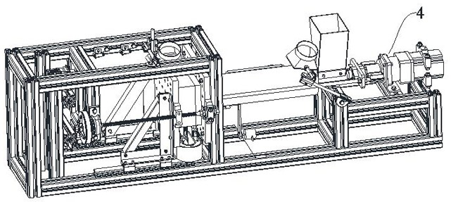
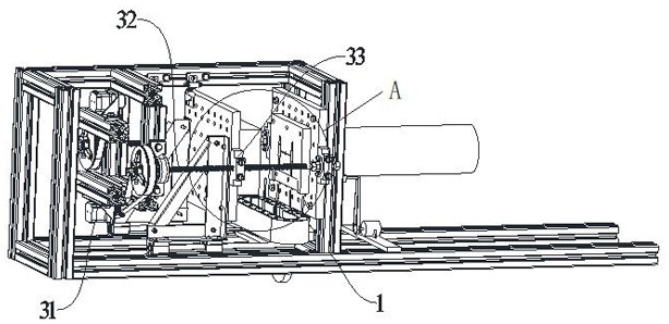
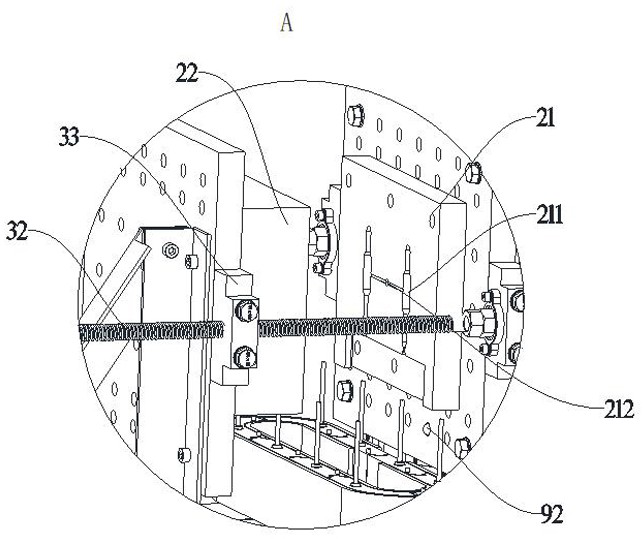
The invention relates to ceramic spark plug forming equipment. The ceramic spark plug forming equipment comprises a frame, a fixed mold, a movable mold, a driving mechanism, a feeding mechanism and anelectrode mounting mechanism. The fixed mold is fixed on the frame, and a first mold cavity is formed in the fixed mold; the movable mold is provided with a second mold cavity, and the second mold cavity can be matched with the first mold cavity to form a complete mold cavity; the driving mechanism is mounted on the frame and can control the movable mold to be close to or far away from the fixedmold; and the charging mechanism can be used for charging raw materials into the die cavity. The spark plug forming equipment has the advantages that by arranging the electrode mounting mechanism, forming of the spark plug and mounting of the electrode can be synchronously completed; and the electrode mounting mechanism can automatically switch the electrodes, so that the spark plug can be continuously processed.

Description

technical field [0001] The invention relates to the field of forming equipment, in particular to a ceramic spark plug forming equipment and a control method thereof. Background technique [0002] Automobile spark plug, commonly known as flame nozzle, its function is to discharge the pulsed high-voltage electricity sent by the high-voltage wire (burner wire), break down the air between the two electrodes of the spark plug, and generate an electric spark to ignite the mixed gas in the cylinder. [0003] Ceramic powder molding can be done by powder pressing or injection molding. Injection molding is characterized by high molding precision and uniform microstructure, which has been widely used. [0004] However, the existing spark plug structures all need to install electrodes, so that the manufacturing needs to be carried out in steps, which greatly reduces the production efficiency. SUMMARY OF THE INVENTION [0005] Based on this, it is necessary to provide a ceramic spark ...

Claims


Application Information

Patent Timeline
Patent Type & Authority Applications(China)
IPC IPC(8): H01T21/02
CPCH01T21/02
Inventor 刘高平
Owner ZHEJIANG WANLI UNIV
Why Eureka
Try Eureka