A battery assembly, battery protection chip and electronic product

A technology for protecting chips and battery components, applied in battery over-discharge protection, battery overcharge protection, battery circuit devices, etc., can solve problems such as increased conduction impedance, low voltage, and reduced effective use time of batteries to avoid potential differences Effect

Active Publication Date: 2022-06-21
XI AN WENXIAN SEMICON TECH CO LTD
View PDF9 Cites 0 Cited by
  • Summary
  • Abstract
  • Description
  • Claims
  • Application Information

AI Technical Summary

Problems solved by technology

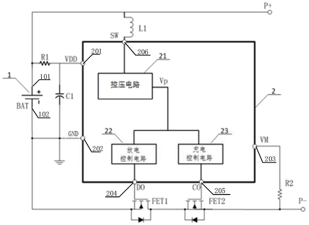
[0003] For the battery charge and discharge protection circuit, it is necessary to detect the charging or discharging current during the charging and discharging process of the rechargeable battery. It is realized by the MOS tube, and the on-off control of the MOS tube needs to be realized by using the voltage of the battery, but in the early stage of charging or late discharge, the voltage of the battery is usually smaller than the full voltage, such as a lithium battery with a rated voltage of 4.2V , in the early stage of charging or late discharge, the voltage of the battery will drop to about 2.5V. The impedance is significantly improved. At this time, the on-resistance of the external MOS may be twice as large as that of the battery when the voltage is 4V. For high-current applications, the loss caused by the on-resistance of the MOS tube will be doubled, and the battery will be reduced faster. The effective use time of the electronic product will also cause heat release at the same time, and the internal temperature of the electronic product will increase accordingly.

Method used


Image

  • A battery assembly, battery protection chip and electronic product
  • A battery assembly, battery protection chip and electronic product
  • A battery assembly, battery protection chip and electronic product

Examples


Embodiment Construction

[0026] In order to facilitate understanding of the present invention, the present invention will be described in more detail below with reference to the accompanying drawings and specific embodiments. Preferred embodiments of the invention are shown in the accompanying drawings. However, the present invention may be embodied in many different forms and is not limited to the embodiments described in this specification. Rather, these embodiments are provided so that a thorough and complete understanding of the present disclosure is provided.

[0027] It should be noted that, unless otherwise defined, all technical and scientific terms used in this specification have the same meaning as commonly understood by those skilled in the technical field of the present invention. The terms used in the description of the present invention are only for the purpose of describing specific embodiments, and are not used to limit the present invention. As used in this specification, the term "...


PUM


Abstract

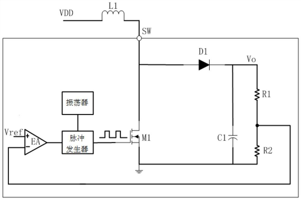
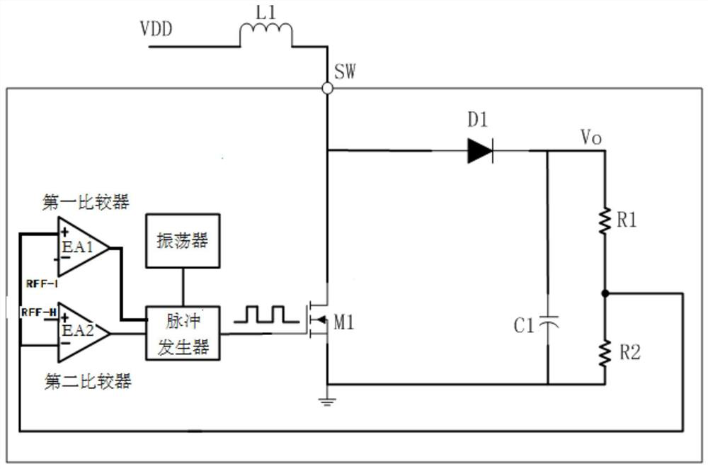
The invention discloses a battery component, a battery protection chip and an electronic product, wherein the battery protection chip includes a power supply pin, a ground pin, an inductance access pin, a current detection pin, a discharge control pin and a charge control pin , the chip also includes a voltage control circuit, a discharge control circuit and a charge control circuit. One end of the inductor is connected to the input end of the voltage control circuit, and the other end is electrically connected to the positive terminal of the battery. The discharge control pin and charge control pin of the battery protection chip They are respectively used to control the first NMOS tube electrically connected to the negative terminal of the battery, and the second NMOS tube electrically connected to the negative terminal of the external power supply. The voltage control circuit generates a stable control voltage, so that the conduction state of the two NMOS tubes is not affected by the battery voltage. The impact of the drop, and effectively avoid the potential difference between the inside and outside of the battery due to the disconnection of the negative terminal of the battery.

Description

technical field [0001] The invention relates to the technical field of battery protection, in particular to a battery assembly, a battery protection chip and an electronic product. Background technique [0002] Rechargeable batteries are widely used in consumer electronic products, and have shown a trend of being built-in as an important part of electronic products. Therefore, the quality and use protection of rechargeable batteries often determine the quality of electronic products. [0003] For the battery charging and discharging protection circuit, during the charging and discharging process of the rechargeable battery, the charging or discharging current needs to be detected. If the current is too large, the charging or discharging needs to be automatically cut off, and the switch that controls the charging and discharging is usually It is realized by the MOS tube. The on-off control of the MOS tube needs to be realized by the voltage of the battery. However, in the ear...

Claims


Application Information

Patent Timeline
Patent Type & Authority Patents(China)
IPC IPC(8): H02J7/00
CPCH02J7/00302H02J7/00306
Inventor 宋利军贺玉婷
Owner XI AN WENXIAN SEMICON TECH CO LTD
Why Eureka
Try Eureka