Vehicle-mounted charging system and vehicle with same

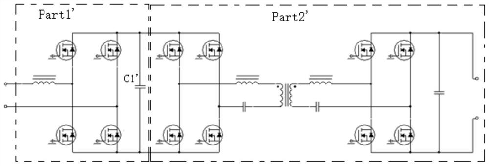
An on-board charging and capacitor technology, applied in the field of vehicles, can solve the problems of electrolytic capacitor C1', such as lifespan, shock resistance, unfavorable system reliability, volume and cost increase, etc., to improve the level of earthquake resistance, reduce cost and volume, and improve reliability Effect

Active Publication Date: 2021-03-30
BYD CO LTD
View PDF8 Cites 0 Cited by
  • Summary
  • Abstract
  • Description
  • Claims
  • Application Information

AI Technical Summary

Problems solved by technology

For this system, in order to provide a stable input DC voltage for the latter stage part2', a large-capacity electrolytic capacitor C1' is required between Part1' and Part2', which increases the volume and cost of the system, and the electrolytic capacitor C1' has a lifespan and is shock-resistant problem, which is detrimental to the reliability of the system

Method used


Image

  • Vehicle-mounted charging system and vehicle with same
  • Vehicle-mounted charging system and vehicle with same
  • Vehicle-mounted charging system and vehicle with same

Examples


Embodiment Construction

[0016] Embodiments of the present invention are described in detail below, and the embodiments described with reference to the drawings are exemplary, and embodiments of the present invention are described in detail below.

[0017] Refer below Figure 2-Figure 4 An on-vehicle charging system according to an embodiment of the present invention will be described.

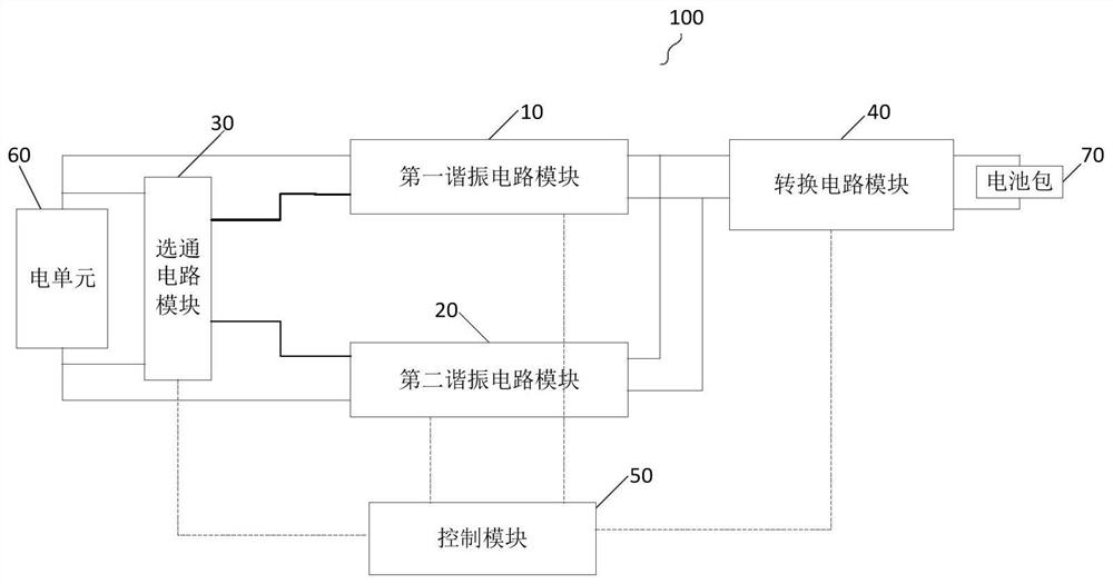
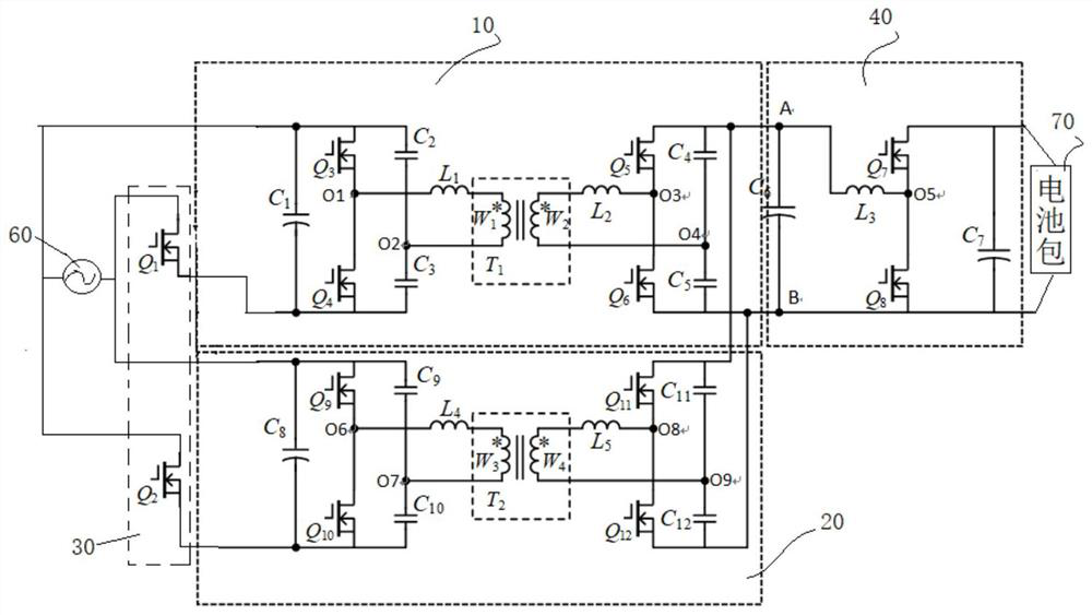
[0018] figure 2 is a block diagram of an on-board charging system according to an embodiment of the present invention, such as figure 2 As shown, the vehicle charging system 100 of the embodiment of the present invention includes a first resonant circuit module 10 , a second resonant circuit module 20 , a gate circuit module 30 , a conversion circuit module 40 and a control module 50 .

[0019] Wherein, the first resonant circuit module 10 is used for converting the electrical signal of the first half cycle of power supply, and the first terminal of the first resonant circuit module 10 is connected to the first te...


PUM


Abstract

The invention discloses a vehicle-mounted charging system and a vehicle with the same. The vehicle-mounted charging system comprises a first resonance circuit module, a second resonance circuit module, a gating circuit module, a conversion circuit module and a control module, wherein the first resonance circuit module is used for carrying out AC-DC conversion processing on an electric signal of afirst half period of power supply; the second resonance circuit module is used for performing alternating current-direct current conversion processing on the electric signal of the second half period;the gating circuit module is used for controlling the first resonance circuit module to be connected with the electric unit or controlling the second resonance circuit module to be connected with theelectric unit; the conversion circuit module is used for performing DC-DC conversion on the input electric signal; the control module is used for controlling the first resonance circuit module in a first half period of power supply or controlling the second resonance circuit module in a second half period of power supply. According to the system and the vehicle, the electrolytic-capacitor-free design is adopted, the cost can be reduced, and the stability is improved.

Description

technical field [0001] The invention relates to the technical field of vehicles, in particular to an on-board charging system and a vehicle with the on-board charging system. Background technique [0002] figure 1 It is a circuit diagram of an on-board charging system in the related art. One end of the system is connected to the power grid, and the other end is connected to the battery pack, including Part1' and Part2' two-stage circuits. During forward charging, Part1' realizes AC-DC conversion and power factor correction, and outputs DC voltage. Part2’ is a DC-DC converter that outputs a suitable voltage to charge the battery pack. For this system, in order to provide a stable input DC voltage for the latter stage part2', a large-capacity electrolytic capacitor C1' is required between Part1' and Part2', which increases the volume and cost of the system, and the electrolytic capacitor C1' has a lifespan and is shock-resistant problem, which is detrimental to the reliabil...

Claims


Application Information

Patent Timeline
Patent Type & Authority Applications(China)
IPC IPC(8): H02J7/10B60L53/20
CPCH02J7/06B60L53/20Y02T10/70Y02T10/7072Y02T90/14Y02T10/92
Inventor 吴昊许兴发刘宇杨柳
Owner BYD CO LTD
Why Eureka
Try Eureka