
Stable high-speed laser cutting machine

A laser cutting machine and fixed-type technology, applied in laser welding equipment, welding/cutting auxiliary equipment, auxiliary devices, etc., can solve problems such as errors, and achieve the effects of convenient movement, reduced friction, and convenient alignment

Inactive Publication Date: 2021-04-02
彭军伟
View PDF6 Cites 0 Cited by
  • Summary
  • Abstract
  • Description
  • Claims
  • Application Information

AI Technical Summary

Problems solved by technology

[0003] However, when the existing positioning equipment used in laser cutting is used, it generally only places the workpiece on the workbench, and then directly processes it by moving the laser cutting machine to the position where it needs to be processed. It is easy to have certain errors when using it, so it is necessary to propose a stable high-speed laser cutting machine

Method used


Image

  • Stable high-speed laser cutting machine
  • Stable high-speed laser cutting machine
  • Stable high-speed laser cutting machine

Examples


Embodiment Construction

[0026] In order to make the technical means, creative features, goals and effects achieved by the present invention easy to understand, the present invention will be further described below in conjunction with specific embodiments.

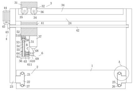
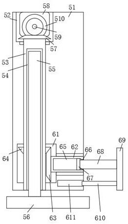
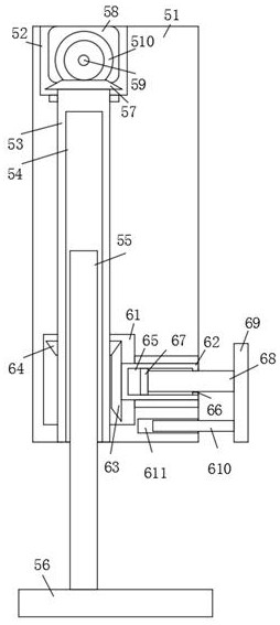
[0027] Such as Figure 1-Figure 8 As shown, a stable high-speed laser cutting machine of the present invention includes a base 1, a mobile support mechanism 2 is arranged on the base 1, a displacement mechanism 3 is arranged on the mobile support mechanism 2, and a displacement mechanism 3 is arranged on the displacement mechanism 3 The driving mechanism 4 and the lower end of the displacement mechanism 3 are fixedly connected with a clamping mechanism 5, and a positioning mechanism 6 is arranged inside the clamping mechanism 5. When in use, the displacement mechanism 3 can be driven by the driving mechanism 4. The mechanism 6 positions the displacement mechanism 3 and aligns the displacement mechanism 3 with the processing position. After that, t...


PUM


Abstract

The invention relates to the field of laser cutting machines, in particular to a stable high-speed laser cutting machine. The stable high-speed laser cutting machine comprises a base, wherein a movable supporting mechanism is arranged on the base; a displacement mechanism is arranged on the movable supporting mechanism; a driving mechanism is arranged on the displacement mechanism; the lower end of the displacement mechanism is fixedly connected with a clamping mechanism; and a positioning mechanism is arranged in the clamping mechanism. The stable high-speed laser cutting machine has the beneficial effects that when the stable high-speed laser cutting machine is used, a positioning plate is aligned to a cutting position of a machined part, so that a laser cutting head is also aligned to the cutting position of the machined part, then a double-head driving motor can be started to drive a clamping plate to descend to clamp the machined part, meanwhile, the positioning plate can be synchronously driven to move towards a mounting seat, and therefore the laser cutting head can be exposed; and the machined part is cut through the laser cutting head, and the laser cutting head is conveniently and quite accurately aligned with the machined part.

Description

technical field [0001] The invention relates to the field of laser cutting machines, in particular to a stable high-speed laser cutting machine. Background technique [0002] Laser cutting is to focus the laser emitted from the laser into a high-power-density laser beam through the optical path system. The laser beam is irradiated on the surface of the workpiece to make the workpiece reach the melting point or boiling point. At the same time, the high-pressure gas coaxial with the beam will melt or gas The metal is blown away, and with the movement of the beam and the relative position of the workpiece, the material will eventually form a slit, so as to achieve the purpose of cutting. [0003] However, when the existing positioning equipment used in laser cutting is used, it generally only places the workpiece on the workbench, and then directly processes it by moving the laser cutting machine to the position where it needs to be processed. Certain errors are prone to occur...

Claims


Application Information

Patent Timeline
Patent Type & Authority Applications(China)
IPC IPC(8): B23K26/38B23K26/70B23K26/08B23K37/04
CPCB23K26/38B23K26/702B23K26/0869B23K37/04
Inventor 彭军伟
Owner 彭军伟
Learn More