Automobile part machining and polishing device

A technology for spare parts and automobiles, which is used in grinding drive devices, metal processing equipment, grinding machines, etc., can solve the problems of affecting the grinding effect, and it is impossible to determine whether the spare parts are polished, so as to improve the accuracy, improve the processing effect, prevent the The effect of too fast

Inactive Publication Date: 2021-04-02
李万刚
View PDF5 Cites 0 Cited by
  • Summary
  • Abstract
  • Description
  • Claims
  • Application Information

AI Technical Summary

Problems solved by technology

[0004] Aiming at the deficiencies of the prior art, the present invention provides a processing and grinding device for auto parts, which solves the problem that the machine cannot determine whether the parts have been polished, which affects the grinding effect

Method used


Image

  • Automobile part machining and polishing device
  • Automobile part machining and polishing device
  • Automobile part machining and polishing device

Examples


Embodiment 1

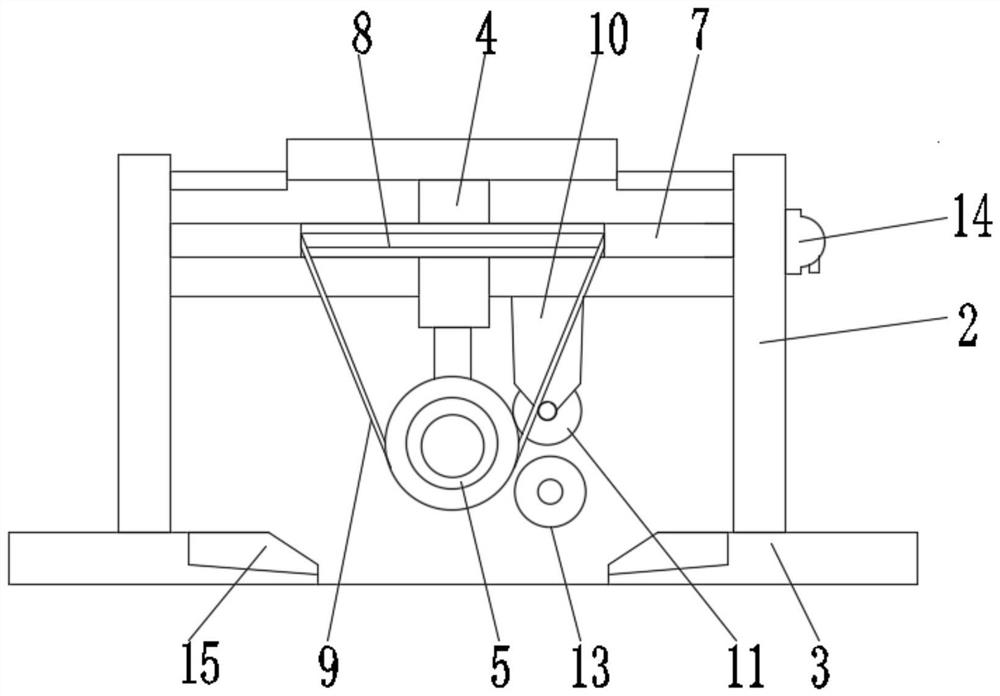
[0035] see Figure 1-3 and 6, the present invention provides a technical solution: a processing and polishing device for auto parts, comprising a base plate 1 and a fixed column 2, the left and right sides of the top of the base plate 1 are respectively fixedly connected to the bottom of the fixed column 2, and the fixed column 2 is opposite A laminate 3 is fixedly connected between one side, and the bottom of the laminate 3 is fixedly connected with a telescopic table 4, and the bottom of the telescopic table 4 is fixedly connected with a mounting rod 5, and the outer surface of the mounting rod 5 is provided with a spreading mechanism 6, and the fixed column 2. A fixed plate 7 is fixedly connected between the opposite sides and directly in front of the laminate 3. The outer surface of the fixed plate 7 is provided with a bar-shaped groove 8, and the inner surface of the bar-shaped groove 8 is slidably connected with a stabilizing mechanism 9. The outer surface of the plate 7...

Embodiment 2

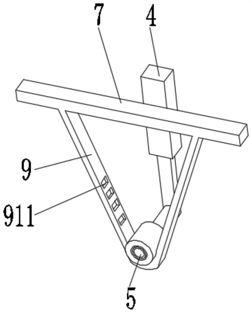
[0041] see figure 1 , 2 , 5, 7, the present invention provides a kind of technical scheme: stabilizing mechanism 9 comprises tension band 91, and the left end of tension band 91 is fixedly connected with the left side of strip groove 8 inside, and the right end of tension band 91 is connected with the inside of strip groove 8 Swipe right to connect.

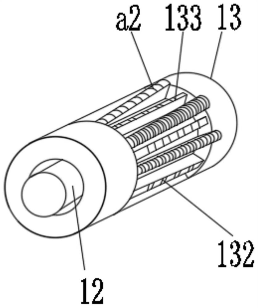
[0042] The outer surface of the tension band 91 is evenly provided with a square groove 911, the inner surface of the square groove 911 is rotatably connected with a damping bearing 912, the outer surface of the damping bearing 912 is fixedly connected with a resistance ring 913, and the outer surface of the resistance ring 913 is evenly provided with an anti-slip sheet 914.

[0043] Stretching mechanism 6 comprises umbrella-shaped cover 61, and the inner side of umbrella-shaped cover 61 is fixedly connected with support rod 62, and one side of support rod 62 away from umbrella-shaped cover 61 is fixedly connected with pressure...


PUM


Abstract

The invention discloses an automobile part machining and polishing device, and relates to the technical field of automobile parts. The automobile part machining and polishing device comprises a bottomplate and fixing columns, the left side and the right side of the top of the bottom plate are fixedly connected with the bottoms of the two fixing columns correspondingly, a laminate is fixedly connected between the opposite sides of the two fixing columns, and a telescopic table is fixedly connected to the bottom of the laminate. Through cooperative use of a stabilizing mechanism and a struttingmechanism, the outer surface of a mounting rod is sleeved with a part, the fixing distance between the mounting rod and the part is adjusted through the strutting mechanism, so that the mounting rodalways plays a role in supporting the part, and the phenomenon that the part is loosened in the machining process is avoided; and through cooperation with a tension belt in the stabilizing mechanism,when the telescopic table moves downwards, a resistance effect is generated on the outer surface of the part, shaking of the part is also avoided, the accuracy of polishing work is improved, the rotating speed of the part can be limited to be too high, and the machining effect is better.

Description

technical field [0001] The invention relates to the technical field of auto parts, in particular to a processing and grinding device for auto parts. Background technique [0002] Auto parts are the various units that make up the whole car and a product that serves the car. There are many kinds of auto parts. With the improvement of people's living standards, people consume more and more cars, and the market for auto parts is getting bigger and bigger. In recent years, auto parts manufacturers are also developing rapidly. [0003] After the existing auto parts are processed, due to the lack of a mechanism for refining the parts, when the parts are deburred, because the machine cannot distinguish whether the parts are completely deburred, excessive grinding may occur, resulting in the shape of the parts being affected. Damage will affect the quality and use effect of spare parts, increase the number of defective products, and generate a lot of waste. Contents of the invent...

Claims


Application Information

Patent Timeline
Patent Type & Authority Applications(China)
IPC IPC(8): B24B9/00B24B41/06B24B47/12B24B41/04
CPCB24B9/00B24B41/06B24B47/12B24B41/04
Inventor 李万刚
Owner 李万刚
Why Eureka
Try Eureka