Marking machine sliding positioning marking device for gas discharge tube machining

A technology of gas discharge tube and scribing device, applied in the direction of manufacturing tools, workshop equipment, etc., can solve the problems of delaying scribing device scribing, inability to scribing with gas discharge tube, and inability to change the angle of the scribing carbon head, etc., to achieve faster The effect of scribing efficiency

Pending Publication Date: 2021-04-02
湖南奕瀚电子科技有限公司
View PDF0 Cites 0 Cited by
  • Summary
  • Abstract
  • Description
  • Claims
  • Application Information

AI Technical Summary

Problems solved by technology

[0005] The purpose of the present invention is: in order to solve the need to take out the gas discharge tube and put a new gas discharge tube into the placement cylinder after marking the gas discharge tube, so as to delay the marking device from marking it and because the marking cannot be changed The angle of the carbon head leads to the problem that it cannot scribe the gas discharge tubes of different sizes. A sliding positioning scribing device for the scribing machine for gas discharge tube processing is provided.

Method used

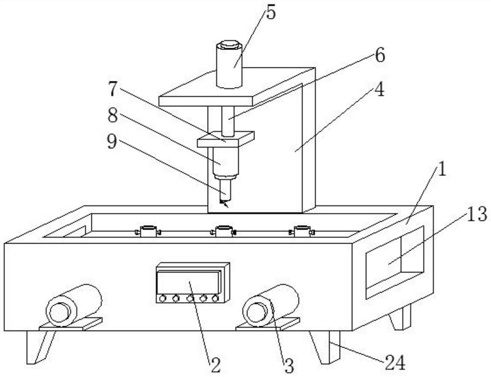
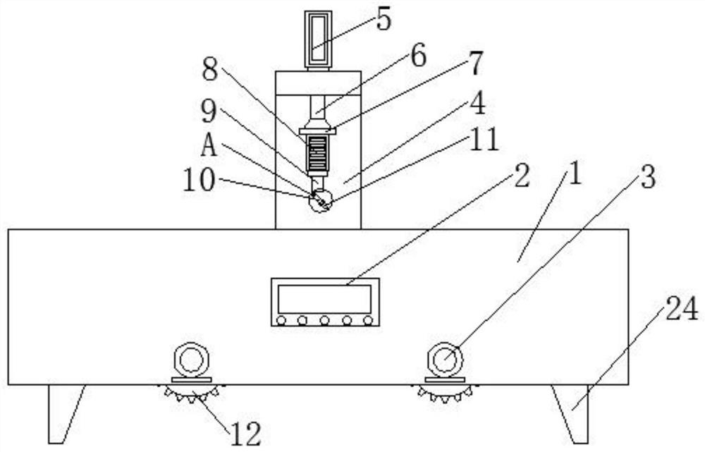
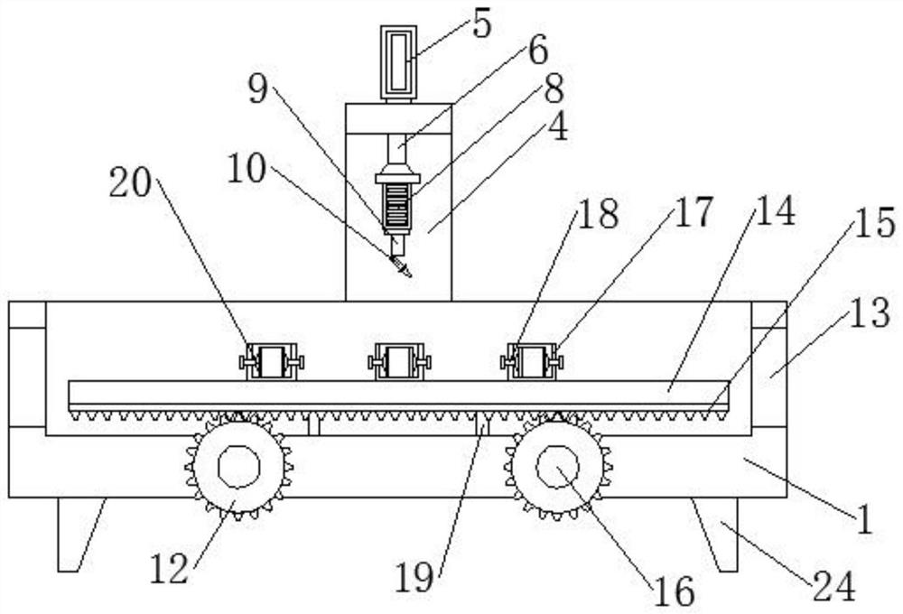

Image

  • Marking machine sliding positioning marking device for gas discharge tube machining
  • Marking machine sliding positioning marking device for gas discharge tube machining
  • Marking machine sliding positioning marking device for gas discharge tube machining

Examples


Embodiment Construction

[0026] The following will clearly and completely describe the technical solutions in the embodiments of the present invention with reference to the accompanying drawings in the embodiments of the present invention. Obviously, the described embodiments are only some, not all, embodiments of the present invention. Based on the embodiments of the present invention, all other embodiments obtained by persons of ordinary skill in the art without making creative efforts belong to the protection scope of the present invention.

[0027] In the description of the present invention, it should be noted that the terms "center", "upper", "lower", "left", "right", "vertical", "horizontal", "inner", "outer" etc. The indicated orientation or positional relationship is based on the orientation or positional relationship shown in the drawings, and is only for the convenience of describing the present invention and simplifying the description, rather than indicating or implying that the referred d...


PUM


Abstract

The invention discloses a marking machine sliding positioning marking device for gas discharge tube machining, and relates to the field of marking devices. The marking machine sliding positioning marking device comprises a device main body, and two first motors are arranged on the outer surface of the device main body. According to the marking machine sliding positioning marking device, by arranging the first motors, rotating shafts, gears, sliding blocks, sliding grooves and a rack, due to the fact that a user puts three gas discharge tubes into three placement cylinders, after marking is carried out on the gas discharge tube in one placement cylinder, the user starts the first motors through an operation table, the first motors work to drive the rotating shafts to rotate, the rotating shafts rotate to drive the gears to rotate, due to the fact that the gears mesh with the rack, the gear can drive the rack to move in the rotating process and drive supporting rods to move at the same time, the supporting rods move to drive the sliding blocks to slide in the sliding grooves, then the corresponding placement cylinder is driven to move, another placement cylinder with one gas discharge tube can conveniently and rapidly move to the position under a marking carbon head, and then the marking carbon head can extend into the corresponding gas discharge tube and carry out marking on theinner wall of the corresponding gas discharge tube.

Description

technical field [0001] The invention relates to the field of scribing devices, in particular to a sliding positioning scribing device for a scribing machine used for gas discharge tube processing. Background technique [0002] Marking machine, a road construction machine that is widely used in roads, squares and runways to draw rules and restrictions such as different restrictions, guidelines and warnings on the flat ground; It has played a huge role in urban planning and road construction, saving the construction period and economic investment of road construction to the greatest extent. [0003] Since the ceramic gas discharge tube is an electric component made by sealing and welding two electrodes made of Fe-Ni-Co alloy to the two metallized ports of the ceramic tube with silver copper solder in a vacuum furnace, before sealing welding The ceramic tube is filled with a mixed inert gas. The inner surface of the ceramic tube is drawn with a pencil and has four carbon wires...

Claims


Application Information

Patent Timeline
Patent Type & Authority Applications(China)
IPC IPC(8): B25H7/04
CPCB25H7/04B25H7/045
Inventor 张一侯
Owner 湖南奕瀚电子科技有限公司
Why Eureka
Try Eureka