
Unmanned equipment control method and control device and unmanned equipment

A control method and equipment technology, applied in the direction of comprehensive factory control, non-electric variable control, control/regulation system, etc., can solve the problems of costing users, cumbersome operation, and a lot of time, so as to reduce detection time, improve detection efficiency, reduce The effect of the operation steps

Pending Publication Date: 2021-04-02
GUANGZHOU XAIRCRAFT TECH CO LTD
View PDF5 Cites 2 Cited by
  • Summary
  • Abstract
  • Description
  • Claims
  • Application Information

AI Technical Summary

Problems solved by technology

[0004] Embodiments of the present invention provide a control method and device for unmanned equipment, and unmanned equipment, to at least solve the problem that unmanned equipment in the related art requires multiple operations before take-off, the operation is cumbersome and takes a lot of time for the user, and it is easy to affect technical issues of user interest

Method used


Image

  • Unmanned equipment control method and control device and unmanned equipment
  • Unmanned equipment control method and control device and unmanned equipment
  • Unmanned equipment control method and control device and unmanned equipment

Examples


Embodiment 1

[0033] According to an embodiment of the present invention, an embodiment of a control method for unmanned equipment is provided. It should be noted that the steps shown in the flow chart of the accompanying drawings can be executed in a computer system such as a set of computer-executable instructions, and , although a logical order is shown in the flowcharts, in some cases the steps shown or described may be performed in an order different from that shown or described herein.

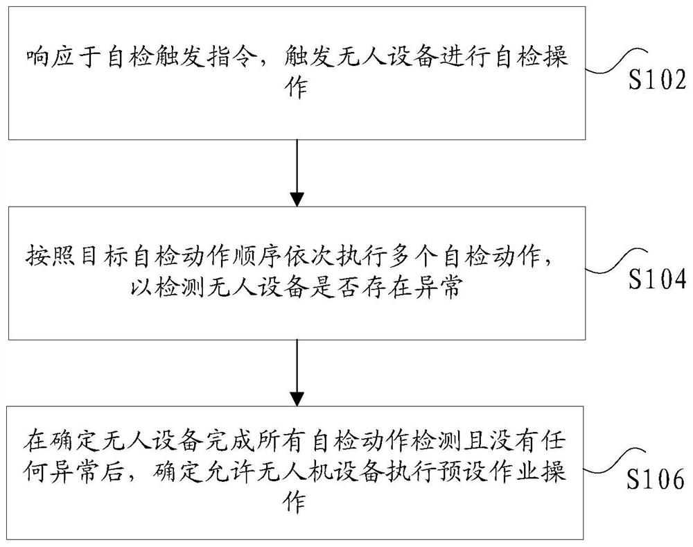
[0034] figure 1 is a flow chart of an optional unmanned device control method according to an embodiment of the present invention, such as figure 1 As shown, the method includes the following steps:

[0035] Step S102, responding to the self-test trigger instruction, triggering the unmanned device to perform a self-test operation;

[0036] Step S104, executing multiple self-inspection actions sequentially according to the target self-inspection action sequence to detect whether there is an abnormali...

Embodiment 2

[0080] An embodiment of the present invention provides a control device for unmanned equipment, and the multiple implementation units contained in the control device correspond to the implementation steps in the first embodiment above.

[0081] Figure 7 is a schematic diagram of an optional unmanned equipment control device according to an embodiment of the present invention, such as Figure 7 As shown, the control device may include: a trigger unit 71, a detection unit 73, and a determination unit 75, wherein,

[0082] A trigger unit 71, configured to trigger the unmanned device to perform a self-check operation in response to a self-check trigger instruction;

[0083] The detection unit 73 is used to perform multiple self-inspection actions sequentially according to the target self-inspection action sequence to detect whether there is an abnormality in the unmanned device;

[0084] The determination unit 75 is configured to determine that the unmanned equipment is allowed...


PUM


Abstract

The invention discloses an unmanned equipment control method and control device, and unmanned equipment. The control method comprises the following steps of: in response to a self-checking trigger instruction, triggering unmanned equipment to perform self-checking operation; sequentially executing a plurality of self-checking actions according to a target self-checking action sequence so as to detect whether the unmanned equipment is abnormal or not; and after it is determined that the unmanned equipment completes all self-checking action detection and has no abnormality, determining that theunmanned equipment is allowed to execute a preset operation. The technical problems that in the related art, unmanned equipment needs to be operated multiple times before takeoff, operation is tedious, a large amount of time of a user needs to be consumed, and the use interest of the user is easily affected are solved.

Description

technical field [0001] The present invention relates to the technical field of equipment control, in particular, to a control method and control device for unmanned equipment, and unmanned equipment. Background technique [0002] In related technologies, with the continuous development of unmanned equipment technology, the types of unmanned equipment continue to increase, and there are types of equipment such as aerial photography unmanned equipment and plant protection unmanned equipment. Unmanned equipment continues to be promoted, but the current unmanned equipment , there are problems of inconvenient installation and operation, especially in terms of operation, many manual inspections are required before the unmanned equipment takes off, such as manual power inspection, communication signal detection, radar status detection, etc. After the inspection, it is necessary to Multiple button confirmations, unmanned equipment inspection and data interaction need to be divided i...

Claims


Application Information

Patent Timeline
Patent Type & Authority Applications(China)
IPC IPC(8): G05D1/10
CPCG05D1/101Y02P90/02
Inventor 陈杰彭斌黄蓉
Owner GUANGZHOU XAIRCRAFT TECH CO LTD
Learn More