Powder cavity filling device

A technology of filling device and cavity, which is applied in the field of powder cavity filling device, to achieve stable working speed and filling effect, and to ensure the effect of working speed and filling effect

Inactive Publication Date: 2021-04-06
XIHUA UNIV
View PDF11 Cites 0 Cited by
  • Summary
  • Abstract
  • Description
  • Claims
  • Application Information

AI Technical Summary

Problems solved by technology

[0003] The purpose of the present invention is to provide a powder cavity filling device, which transports the powder through a conveyor belt, and then sets a plurality of cavity holes, so that the powder can be continuously and effectively filled, fully ensuring stable working speed and filling effect, and solving the problem of There are many deficiencies in conventional packing devices

Method used


Image

  • Powder cavity filling device
  • Powder cavity filling device

Examples


Embodiment 1

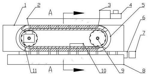
[0022] A powder cavity filling device, including a filling device and a transport device;

[0023] Described packing device comprises sealing block 1, conveyer belt 5, hopper 2, motor A4 and vibrating device 3, is provided with mounting groove on the side of described sealing block 1, two groove walls of described mounting groove are connected with sealing block respectively The top surface and the bottom surface of 1 are connected, the bottom of the installation groove is connected with the side of the sealing block 1, the outer wall of the conveyor belt 5 is in contact with the groove wall of the installation groove, and pulleys 9 are provided at both ends of the inner wall of the conveyor belt 5. The pulley 9 cooperates with the inner wall of the conveyor belt 5, a motor B11 is installed on the side of the pulley 9, the pulley 9 is electrically connected with the motor B11, and the outer wall of the conveyor belt 5 is provided with several evenly spaced cavity holes. The bo...

Embodiment 2

[0028] A specific implementation description is made for the operation mode in Embodiment 1.

[0029] Such as figure 1 As shown, in the present invention, a sensor 10 is arranged on the base 8, which can detect whether the cavity hole on the conveyor belt 5 corresponds to the cavity between the two bars, and when there is a deviation, the motor B11 is used to control the belt. Wheel 9 carries out speed regulation.


PUM


Abstract

A powder cavity filling device comprises a filling device body and a conveying device. A mounting groove is formed in the side face of a sealing block, the outer wall of a conveying belt makes contact with the groove wall of the mounting groove, belt wheels are arranged at the two ends of the inner wall of the conveying belt correspondingly, the belt wheels are matched with the inner wall of the conveying belt, and a motor B is installed on the side face of one belt wheel. A plurality of cavity holes are formed in the outer wall of the conveying belt at even intervals, the bottom of a trough is matched with an opening in the top of the sealing block, a motor A and a vibration device are installed at the top of the sealing block, the conveying device comprises a base, and the base is arranged at the bottom of the sealing block. A plurality of bars which are uniformly arranged at intervals and move at a constant speed are arranged on the top surface of the base. According to the powder cavity filling device, the problems of many defects of a conventional filling device are solved.

Description

technical field [0001] The invention relates to the field of cavity filling, in particular to a powder cavity filling device. Background technique [0002] The packing is mainly divided into bulk packing and structured packing. The performance of the packing mainly depends on the large surface area, the uniform distribution performance of the packing surface, the uniform distribution of the air flow in the packing layer, and the large void ratio in the packing. The traditional filling devices are single-head three-dimensional screw type or measuring cup type, and their work efficiency is not high and the filling speed is slow. For example, the Chinese patent "a powder filling machine" published on April 16, 2015 (application number: 201520229275.2) uses springs to fix the bottom plate on the conveyor belt for powder filling, which can prevent the powder from falling from a high place and cause too much impact phenomenon, but its feeding follow-up time is short. The Chinese...

Claims


Application Information

Patent Timeline
Patent Type & Authority Applications(China)
IPC IPC(8): B65B1/04B65B37/16B65B37/00B65D88/66
CPCB65B1/04B65B37/16B65B37/005B65D88/66
Inventor 吴杰唐绍禹张辉邓兵兵黄禹铭
Owner XIHUA UNIV
Why Eureka
Try Eureka