

Side face pressing device
A technology of pressing device and cylinder, applied in transportation and packaging, conveyors, mechanical conveyors, etc., can solve the problems of large welding production workload, difficult to guarantee processing requirements, high labor intensity, etc., and achieve reasonable component design and structure. Compact, well-structured and ingenious effect
- Summary
- Abstract
- Description
- Claims
- Application Information
AI Technical Summary
Problems solved by technology
Method used
Image

Examples
Embodiment Construction
[0024] The present invention will be further described below in combination with specific embodiments and accompanying drawings.
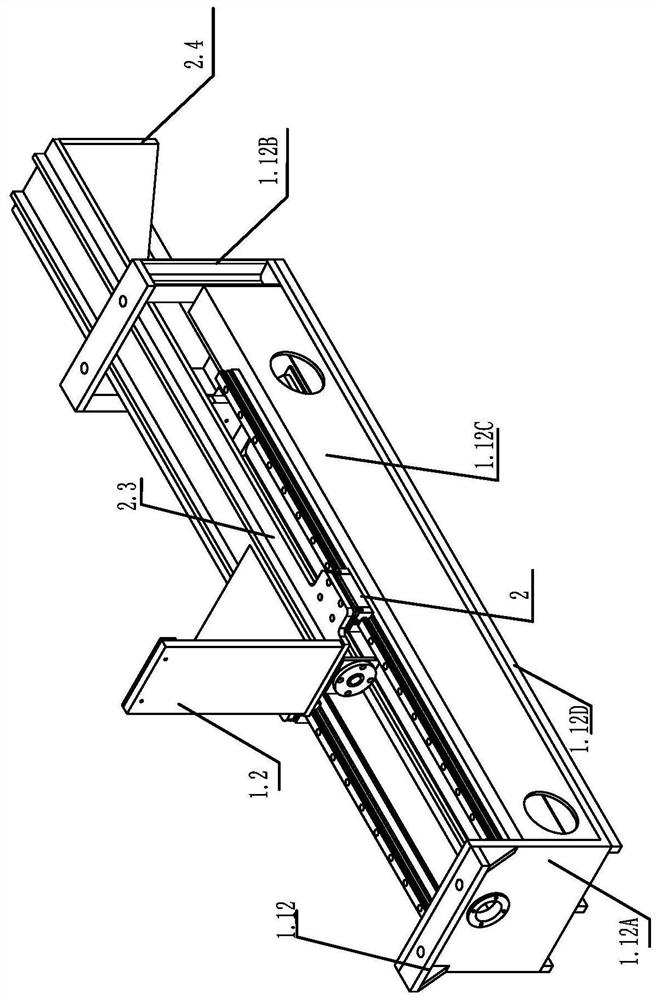
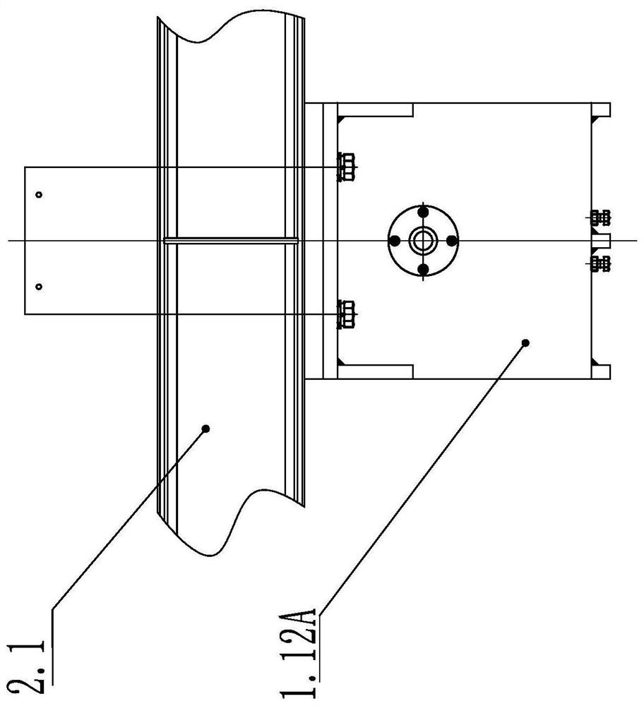
[0025] As shown in the figure: a side pressing device, the pressing device is fixed under the conveying track frame 2.1,
[0026] It includes a frame 1.12, a push frame 1.2, and a direct guide rail pair 1.13;
[0027] The frame includes a left frame body 1.12A and a right frame body 1.12B, as well as front and rear side plates 1.12C connecting the left and right frame bodies and a bottom plate 1.12D;
[0028] The linear guide rail pair 1.13 is respectively assembled on the front and rear side panels 1.12C, the linear guide rail pair 1.13 is slidably provided with a slider 2, the bottom of the push frame 1.2 is vertically provided with a connecting plate 2.3, and the bottom of the connecting plate is fixed to the slider 2 connect;
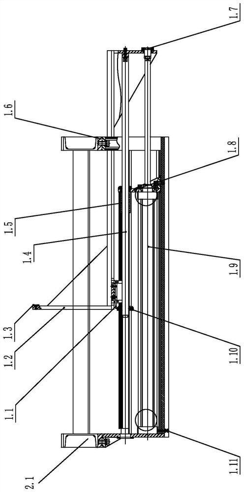
[0029] A pushing frame assembly is assembled in the frame.
[0030] The push frame assembly includes cylinder 1.9, ...
PUM
 Abstract
Description
Claims
Application Information