
A cooling crystallization box

A technology of cooling crystallization and box body, applied in the direction of heat exchange cooling crystallization, solution crystallization, crystallization adjustment/control, etc., can solve the problems of difficulty in filtration and separation, damage to grains by stirring fins, uneven grains, etc.

Active Publication Date: 2022-02-11
MYANDE GRP CO LTD
View PDF0 Cites 0 Cited by
  • Summary
  • Abstract
  • Description
  • Claims
  • Application Information

AI Technical Summary

Problems solved by technology

[0003] The currently commonly used crystallizer structure is a cylindrical tank with a built-in fixed cooling pipe or cooling plate (also with an additional outer jacket), a stirrer in the center, and a cooling pipe or outer jacket near the tank wall. The cooling pipe cannot be arranged, and the heat transfer is affected
In such a structure, the cooling area is unevenly distributed in space, and the stirring intensity in the central area is high. The stirring effect of the tank wall area will be weakened due to the barrier of the cooling pipe or the cooling plate, and the heat transfer effect will become poor, resulting in a temperature gradient on the cross section. Inhomogeneous grain size, crystallization efficiency and effect are affected
Improving by increasing the stirring intensity will bring damage to the crystal grains by the stirring fins, affect the crystal growth, and make subsequent filtration and separation difficult.
[0004] In recent years, there have been crystallization tanks in which supercooling tubes are densely arranged in the cylinder and rotate around the central axis. Although the cooling area on the cross section is uniform, it cannot overcome the influence of shear and mixing intensity caused by the difference in rotational speed in the diameter direction. , the application in engineering is subject to certain restrictions

Method used


Image

  • A cooling crystallization box
  • A cooling crystallization box
  • A cooling crystallization box

Examples


Embodiment Construction

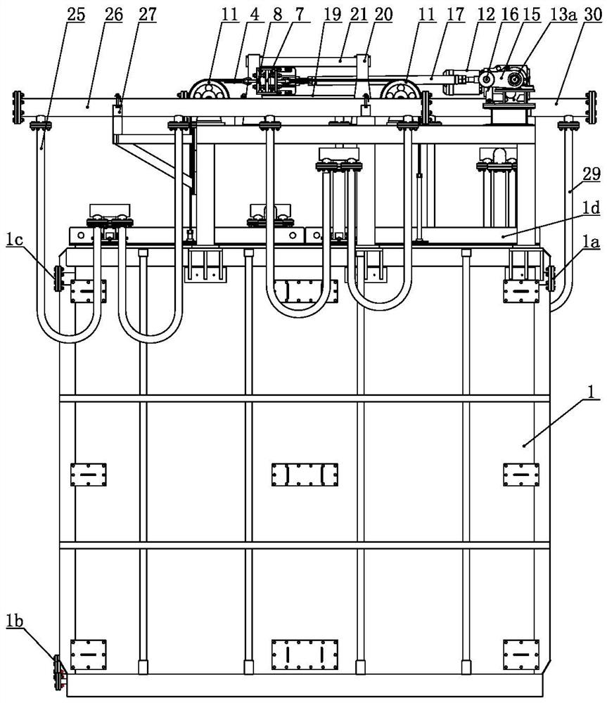
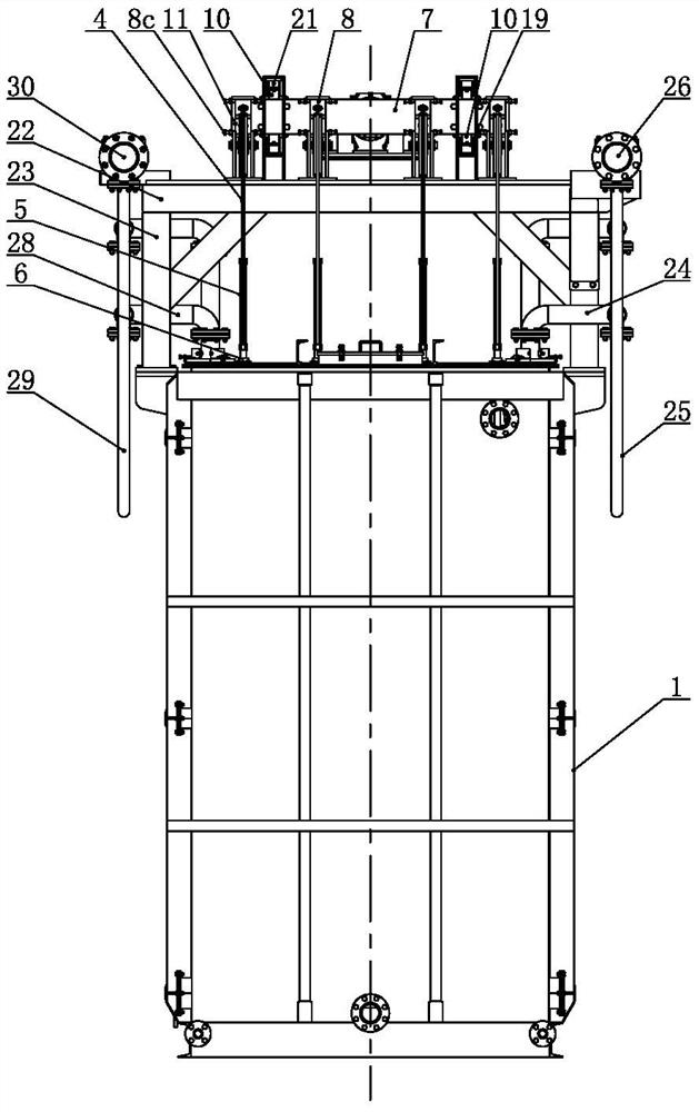
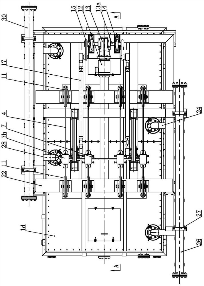
[0029] like Figure 1 to Figure 6 As shown, the cooling crystallization box of the present invention comprises a square box body 1, the upper end of the box body 1 is provided with a top cover 1d, the upper part of the right side wall of the box body 1 is provided with an oil inlet 1a, and the lower part of the left side wall of the box body 1 is provided with an oil inlet 1a. There is an oil outlet 1b, and the inner cavity of the box body 1 is provided with two rows of square cooling tube bundles 2 on the left and right, and the two rows of square cooling tube bundles 2 can reciprocate vertically.

[0030] The oil enters the inner cavity of the box from the oil inlet 1a on the upper right side of the box body 1, and the cooling water enters the two rows of square cooling tube bundles 2 to cool the oil at the same time. The oil outlet 1b at the lower part of the side wall is discharged, usually intermittent oil inlet and outlet. Two rows of square cooling tube bundles 2 fill ...


PUM


Abstract

The invention relates to a cooling crystallization box. The upper end of the square box is provided with a top cover, the upper part of the right side wall of the box is provided with an oil inlet, the lower part of the left side wall is provided with an oil outlet, and the inner cavity of the box is provided with two square cooling tube bundles. The two square cooling tube bundles can reciprocate vertically respectively. Each row of square cooling tube bundles includes four vertical pipes parallel to each other. Standpipe 1, vertical pipe 2, vertical pipe 3 and vertical pipe 4 stand in the four corners of the rectangle in turn, vertical pipe 1 and vertical pipe 3 are diagonal distribution, the top of standpipe 1 is connected with an upwardly extending tube bundle inlet pipe, the top of standpipe 3 is connected with an upwardly extending tube bundle outlet pipe, and there are multiple left confluences extending along the front and rear directions between standpipe 1 and standpipe 2 Horizontal pipes, vertical pipe four and vertical pipe three are connected with multiple right confluence horizontal pipes extending in the front and back directions, and the left confluence horizontal pipes on the same floor are respectively connected to the right confluence horizontal pipes through multiple cooling branch pipes extending horizontally to the right . The crystallization box integrates cooling and stirring, has a large cooling area, and has no heat exchange blind area.

Description

technical field [0001] The invention relates to a cooling crystallization box, which can be used for cooling crystallization in food processing, and belongs to the technical field of cooling crystallization equipment. Background technique [0002] Cooling crystallization is to use the difference in melting point of each component in the material or the difference in mutual solubility at different temperatures, and the crystals are precipitated by controlling the cooling speed and temperature, and then separated by filtration. [0003] The currently commonly used crystallizer structure is a cylindrical tank with a built-in fixed cooling pipe or cooling plate (also with an additional outer jacket), a stirrer in the center, and a cooling pipe or outer jacket near the tank wall. The cooling pipe cannot be arranged, and the heat exchange is affected. In such a structure, the cooling area is unevenly distributed in space, and the stirring intensity in the central area is high. Th...

Claims


Application Information

Patent Timeline
Patent Type & Authority Patents(China)
IPC IPC(8): B01D9/02
CPCB01D9/0013B01D9/0059B01D9/0063
Inventor 杭明张鹏程周二晓
Owner MYANDE GRP CO LTD
Learn More