Laser rust removal steel component surface roughness control method

A surface roughness and control method technology, applied in laser welding equipment, manufacturing tools, welding equipment, etc., can solve problems such as unfavorable coating operations, burns, uneven surface quality, etc.

Active Publication Date: 2021-04-09
ZHENGZHOU RAILWAY VOCATIONAL & TECH COLLEGE
View PDF8 Cites 0 Cited by
  • Summary
  • Abstract
  • Description
  • Claims
  • Application Information

AI Technical Summary

Problems solved by technology

Further studies have found that the surface roughness of the steel surface is irradiated multiple times or repeatedly, and the surface roughness changes firstly (rust spots are removed) and then becomes large (surface burns). There are certain requirements for surface roughness, and the current technology cannot take into account the control of surface roughness in addition to rust removal
[0004] In addition, the surface corrosion of large-scale steel components is often caused by rainwater or poor moisture removal, and the distribution of rust is not uniform. No rust or thin rust will be burned, resulting in uneven surface quality, which is not conducive to subsequent painting operations

Method used


Image

  • Laser rust removal steel component surface roughness control method
  • Laser rust removal steel component surface roughness control method
  • Laser rust removal steel component surface roughness control method

Examples


Embodiment Construction

[0061] The present invention will be further described below in conjunction with embodiment.

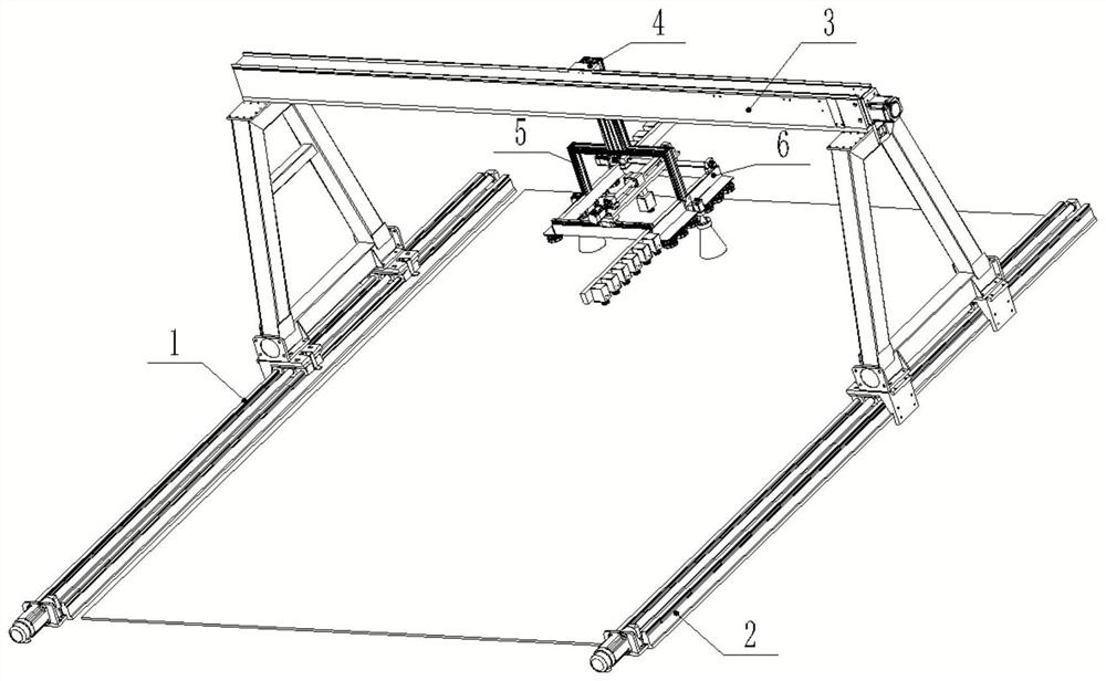
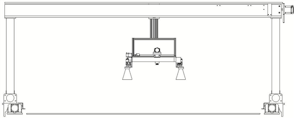
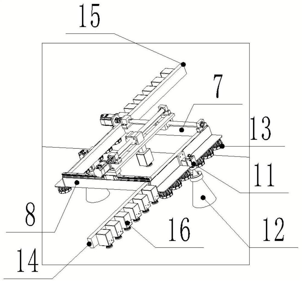
[0062] Such as Figure 1-8 As shown, according to a method for controlling the surface roughness of laser derusting steel components of the present application, the derusting device used includes a propulsion mechanism composed of a left rail 1 and a right rail 2, and a gantry frame connected to the propulsion mechanism by transmission. 3. The boom 4 that can be driven to move along the crossbeam of the gantry frame 3, a suspension is fixedly connected to the bottom of the boom 4, and a working head is installed on the suspension; the working head includes a square frame 6, and the square frame 6 is composed of Four frame bars with the same length are composed of rear frame bar 8, front frame bar 7, left frame bar 9 and right frame bar 10, cameras are respectively installed at the midpoints of left frame bar 9 and right frame bar 10 , the left frame bar 9 and the right frame bar 10 ...


PUM


Abstract

The invention provides a laser rust removal steel component surface roughness control method. An adopted rust removal device comprises a propelling mechanism composed of a left rail and a right rail, a portal frame connected to the propelling mechanism in a transmission mode and a suspension arm capable of being driven to move along a cross beam of the portal frame, a suspension is fixedly connected to the lower portion of the suspension arm, a working head is installed on the suspension, the working head comprises a square frame, the square frame is composed of four frame strips with the same length, the four frame strips are the rear frame strip, the front frame strip, the left frame strip and the right frame strip respectively, cameras are installed at the midpoints of the left frame strip and the right frame strip respectively, an illuminating lamp set is installed below the left frame strip and the right frame strip, and the illuminance in the shooting ranges of the corresponding cameras is uniform.

Description

technical field [0001] The application relates to the field of pretreatment of civil engineering building materials, in particular to a method for controlling the surface roughness of laser derusting steel components. Background technique [0002] Steel components are commonly used construction engineering materials, which are installed in construction after factory prefabrication, and then need to be painted. Different construction occasions have different requirements for the surface quality of steel components. For example, for anti-corrosion and anti-aging requirements, it is necessary to remove the rust on the surface of steel components due to long storage time or unsatisfactory construction environment. At the same time, in order to make the coating The surface of the rust-removed steel member needs to meet a certain surface roughness requirement. [0003] There is a clean and environmentally friendly derusting method, which adopts the method of emitting laser pulses...

Claims


Application Information

Patent Timeline
IPC IPC(8): B23K26/36B23K26/082B23K26/70
CPCB23K26/36B23K26/082B23K26/0884B23K26/702
Inventor 齐悦谢小山张月玥陈彦恒孙洪硕周郑刘阳王大帅耿文燕马志芳
Owner ZHENGZHOU RAILWAY VOCATIONAL & TECH COLLEGE
Why Eureka
Try Eureka