Pouring equipment for preparing fused quartz ceramic and pouring process of pouring equipment
A technology of ceramic preparation and fused silica, which is applied in manufacturing tools, ceramic forming machines, ceramic forming workshops, etc., can solve the problems of inability to preheat pipelines, inability to effectively avoid cooling of molten liquid, and reduce device working efficiency, etc., to achieve improvement adaptive effect
- Summary
- Abstract
- Description
- Claims
- Application Information
AI Technical Summary
Problems solved by technology
Method used
Image


Examples
Embodiment 1
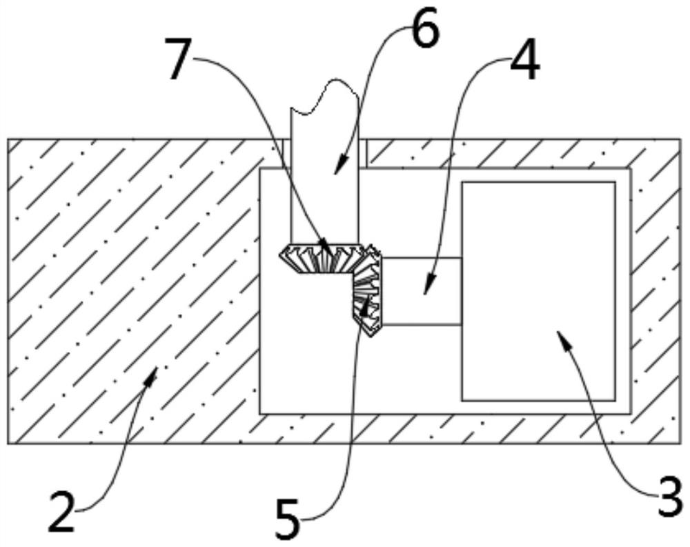
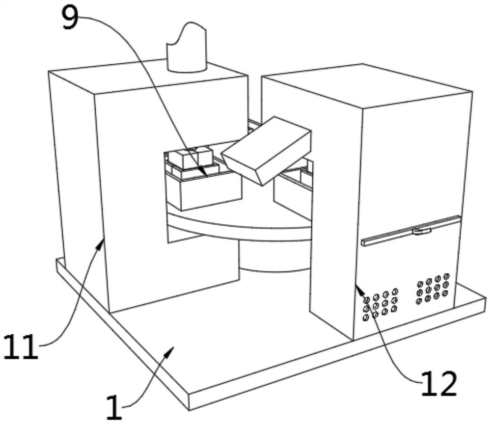
[0048] see Figure 1-10 According to an embodiment of the present invention, a pouring equipment for preparing fused silica ceramics and a pouring process thereof include a fixed base 1, the top of the fixed base 1 is sequentially fixed with a fixed column 2, a cooling mechanism 12 and a main body 11, the One side inside the fixed column 2 is fixed with a first motor 3, the output end of the first motor 3 is fixed with a first rotating rod 4, and the end of the first rotating rod 4 away from the first motor 3 is fixed with a second A bevel gear 5, the end of the fixed column 2 away from the fixed base 1 is rotatably connected with a second rotating rod 6 through a bearing, and the end of the second rotating rod 6 close to the fixed column 2 is fixed with a second bevel gear 7. The end of the second rotating rod 6 away from the second bevel gear 7 is fixed with a fixed plate 8, and the end of the fixed plate 8 far away from the second rotating rod 6 is evenly fixed with a fixin...
Embodiment 2
[0051] see Figure 1-10 , the fixed mechanism 9 includes a fixed box 26, a second motor 27, a third bevel gear 28, a rotating shaft 29, a fourth bevel gear 30, a fixed plate 31, a second switch 32 and a limit rod 33, the fixed box The bottom end of 26 inside is fixed with second motor 27, and the output end of described second motor 27 is fixed with the 3rd bevel gear 28, and the two ends of described fixed box 26 inner sides are connected with rotating shaft 29 through bearing rotation, and described rotating A fourth bevel gear 30 is fixed on the end of the shaft 29 close to the second motor 27, a second switch 32 is fixed on one side of the fixed box 26, and a fixed plate 31 is movably connected to the peripheral side of the rotating shaft 29. Both sides of the bottom end of the fixed plate 31 are movably connected with the limit rods 33, and the peripheral side of the rotating shaft 29 is uniformly provided with threads, and the fixed plate 31 and the rotating shaft 29 are...
Embodiment 3
[0054] see Figure 1-10 , the cooling mechanism 12 includes a support frame 18, air holes 19, a first fan 20, a second fan 21, a fixed rod 22, a third fan 23, a cooling plate 24, a groove 25, a filter plate 34, a handle 35, a control panel and insulation layer, the inner wall of the top of the support frame 18 is fixed with an insulation layer, and one side of the bottom end of the support frame 18 is evenly distributed with air holes 19, and the inside of the bottom end of the support frame 18 is close to the air hole 19. One side is fixed with a first fan 20, and the bottom end of the support frame 18 is located at the top of the first fan 20, and a second fan 21 is fixed, and the bottom end of the support frame 18 is evenly fixed with fixed rods 22, And the fixing rod 22 is located at the top of the second fan 21, the support frame 18 is provided with a groove 25 on the side close to the air hole 19, and the groove 25 is located at the top of the air hole 19 The inside of ...
PUM
 Abstract
Description
Claims
Application Information
 - R&D
- Intellectual Property
- Life Sciences
- Materials
- Tech Scout
- Unparalleled Data Quality
- Higher Quality Content
- 60% Fewer Hallucinations
Browse by: Latest US Patents, China's latest patents, Technical Efficacy Thesaurus, Application Domain, Technology Topic, Popular Technical Reports.
© 2025 PatSnap. All rights reserved.Legal|Privacy policy|Modern Slavery Act Transparency Statement|Sitemap|About US| Contact US: help@patsnap.com