Oil return system and oil return method thereof

A technology of oil return system and engine oil, which is applied in the direction of engine components, machines/engines, mechanical equipment, etc. It can solve the problems of low reliability, large size, and easy blockage of one-way valves, etc., and achieves simple structure and increased layout freedom degree of effect

Active Publication Date: 2021-04-09
FAW JIEFANG AUTOMOTIVE CO
View PDF9 Cites 0 Cited by
  • Summary
  • Abstract
  • Description
  • Claims
  • Application Information

AI Technical Summary

Problems solved by technology

[0004] However, as the service time of the diesel engine increases, the negative pressure in the suction pipe of the diesel engine will gradually increase due to the clogging of the air filter of the diesel engine or other reasons, so that the gas separated by the oil-gas separator can be sucked in with greater suction. At the same time, it is easy to pour the oil from the oil pan into the oil-air separator, making it difficult to return the oil, thus affecting the performance of the entire diesel engine
[0005] At present, in order to solve the above problems, a one-way valve is added while increasing the height of the oil-gas separator to increase the difficulty of sucking the oil back into the oil-gas separator from the oil pan, so as to improve the separation efficiency of the oil-gas separator; but the height The higher oil-air separator is easily limited by the overall height of the engine, which is not convenient for the overall layout of the engine; and the check valve is prone to blockage during long-term use, making its work less reliable

Method used


Image

  • Oil return system and oil return method thereof
  • Oil return system and oil return method thereof
  • Oil return system and oil return method thereof

Examples


Embodiment 1

[0039] In this embodiment, an oil return system and an engine including the oil return system are proposed. Among them, the oil return system can prevent the oil from being sucked back into the oil-air separator from the oil pan, and can ensure that no air will enter the negative pressure oil filter, and has the characteristics of simple structure and high reliability.

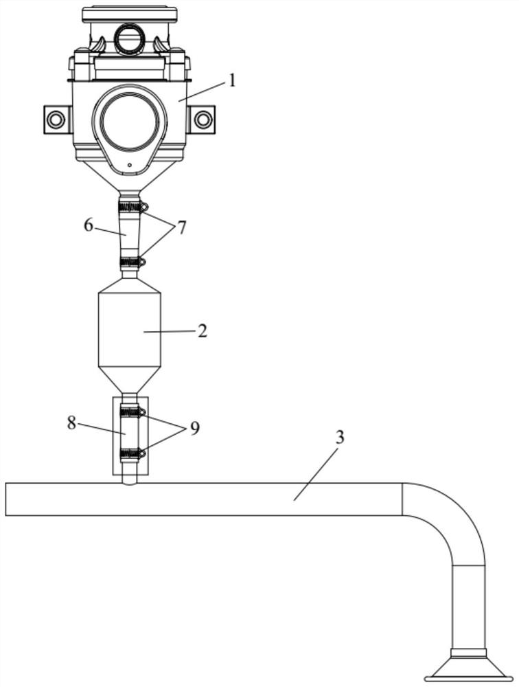
[0040] Specifically, such as figure 1As shown, the oil return system includes an oil-air separator 1 , a negative pressure oil filter 3 and a one-way float valve 2 . Among them, one end of the oil-gas separator 1 is connected with the crankcase to separate the engine oil in the mixed gas discharged from the crankcase; the one-way float valve 2 is connected with the oil-gas separator 1 and the negative pressure oil filter 3, and the negative pressure oil collector The other end of the filter 3 is inserted under the oil level of the oil pan, and the negative pressure oil filter 3 is used to filter the oil in th...

Embodiment 2

[0052] In this embodiment, a method of oil return using the oil return system in Embodiment 1 is proposed. The oil return method of the oil return system includes the following steps:

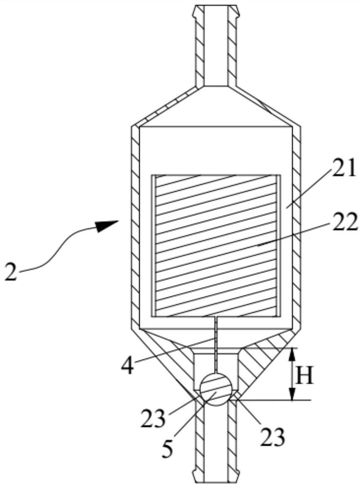
[0053] S1, discharge part of the oil in the oil storage chamber 21, so that the gravity ball 5 moves vertically downward under the action of its own gravity to fit the sealing surface 23, so as to block the one-way float valve 2, so that the one-way float valve 2 is isolated from the negative pressure oil filter 3, thereby preventing the gas in the oil-gas separator 1 from entering the negative pressure oil filter 3.

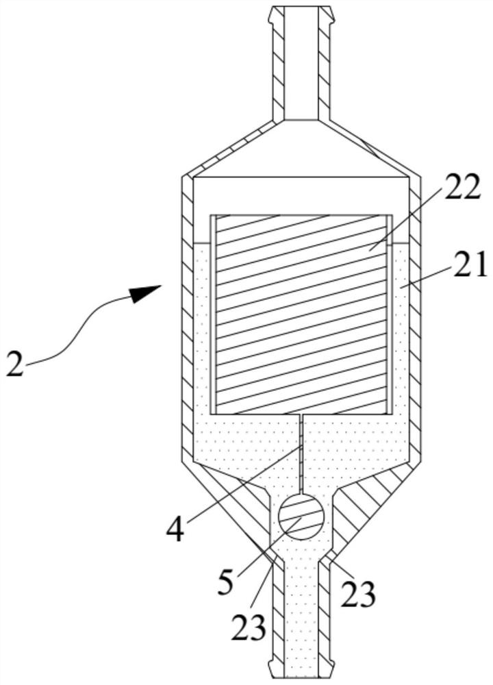
[0054] S2, the oil separated by the oil-gas separator 1 gradually flows into the oil storage chamber 21 until the float 22 can drive the gravity ball 5 to move vertically upward under the action of the buoyancy of the oil, so that the gravity ball 5 is separated from the sealing surface 23 , to open the one-way float valve 2, so that the oil in the oil storage chamber 21 flows in...


PUM


Abstract

The invention discloses an oil return system and an oil return method thereof, and belongs to the technical field of engines. The oil return system comprises an oil-gas separator, a negative pressure engine oil suction filter, a one-way float valve and a gravity ball; one end of the oil-gas separator is connected with a crankcase; one end of the negative-pressure engine oil suction filter is inserted below the engine oil liquid level of an oil pan and used for filtering engine oil; the one-way float valve is connected with the oil-gas separator and the negative-pressure engine oil suction filter; an oil storage cavity used for storing engine oil is formed in the one-way float valve, a sealing area is arranged on the inner wall of the end, close to the negative-pressure engine oil suction filter, of the oil storage cavity in a protruding mode, the one-way float valve comprises a float, and the float can only float in the oil storage cavity in the vertical direction; and the gravity ball is located in the sealing area and used for being attached to or separated from the sealing face so as to block or open the one-way float valve. The oil return system has the advantages that the engine oil can be prevented from being sucked back, and air is prevented from entering the negative-pressure engine oil suction filter.

Description

technical field [0001] The invention relates to the technical field of engines, in particular to an oil return system and an oil return method thereof. Background technique [0002] When the diesel engine is working, with the continuous reciprocating movement of the piston, a small amount of high-temperature and high-pressure gas will continue to escape into the crankcase from the gap between the piston ring and the cylinder of the combustion chamber of the diesel engine; The high-pressure gas has complex components and cannot be directly discharged to the atmosphere. Therefore, it is necessary to use the crankcase oil-gas separation system to carry out a closed cycle of the gas in the engine to prevent the high-temperature and high-pressure gas from being directly discharged to the atmosphere. [0003] The oil-gas separator separates the engine oil from the high-temperature and high-pressure gas that has entered the crankcase, and returns the engine oil to below the liquid ...

Claims


Application Information

Patent Timeline
Patent Type & Authority Applications(China)
IPC IPC(8): F01M13/04F01M13/00
CPCF01M13/04F01M13/00
Inventor 阮志强李晶晶韩旭东沈华中杨海涛魏文汤旭财张青巧吕小井刘桂玲
Owner FAW JIEFANG AUTOMOTIVE CO
Why Eureka
Try Eureka