Engine exhaust temperature control method and device and engine exhaust temperature control system

A control method and engine technology, applied in engine control, combustion engine, machine/engine, etc., can solve the problems of increasing the production cost of the engine exhaust temperature control system, increasing environmental pollution, increasing waste of resources, etc.

Active Publication Date: 2021-04-09
SAIC MOTOR
View PDF10 Cites 4 Cited by
  • Summary
  • Abstract
  • Description
  • Claims
  • Application Information

AI Technical Summary

Problems solved by technology

Among them, since the throttle valve installed at the engine intake port reduces the exhaust temperature of the engine by greatly increasing the intake air volume, the excess air coefficient is greatly increased. Therefore, when the excess air coefficient is too large, it is easy to cause insufficient combustion in the engine. The particulate matter in the exhaust gas will increase, which will easily lead to an increase in waste of resources and an increase in environmental pollution
In addition, both of the above two engine exhaust temperature control systems need additional throttle valves or cooling devices to achieve cooling control of the engine exhaust temperature, which not only increases the difficulty of temperature control of the engine exhaust temperature control system, but also increases the Production cost of engine exhaust temperature control system

Method used


Image

  • Engine exhaust temperature control method and device and engine exhaust temperature control system
  • Engine exhaust temperature control method and device and engine exhaust temperature control system
  • Engine exhaust temperature control method and device and engine exhaust temperature control system

Examples


Embodiment 1

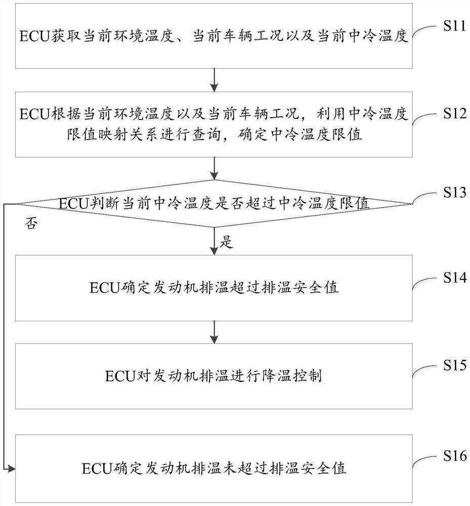
[0061] see figure 1 , which is a flow chart of the engine exhaust temperature control method provided by the embodiment of the present application.

[0062] The engine exhaust temperature control method provided in the embodiment of the present application includes steps S11-S16:

[0063] S11: The ECU obtains the current ambient temperature, the current vehicle operating condition, and the current intercooler temperature.

[0064] The current ambient temperature refers to the ambient temperature outside the engine of the vehicle at the current moment. For example, the current ambient temperature is 25°C.

[0065] The current vehicle operating condition refers to parameters related to engine operation at the current moment. For example, current vehicle operating conditions may include current engine speed and current injection quantity of the engine oil pump.

[0066] The current intercooler temperature refers to the temperature of the gas discharged from the intercooler at...

Embodiment 2

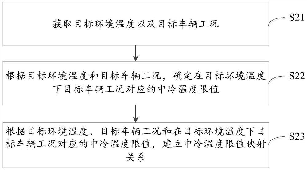
[0082] The intercooler temperature limit mapping relationship can be pre-built, and the embodiment of the present application also provides a method for constructing the intercooler temperature limit mapping relationship, and this method will be used in Method embodiment two For detailed introduction, please refer to the technical details Method embodiment two .

[0083] In addition, the embodiment of the present application does not limit the construction time of the intercooler temperature limit mapping relationship, and the intercooler temperature limit mapping relationship only needs to be constructed before step S12 is executed.

[0084] The above is the specific implementation manner of step S12.

[0085] S13: The ECU judges whether the current intercooler temperature exceeds the intercooler temperature limit, if yes, execute steps S14-S15; if not, execute step S16.

[0086] In the embodiment of the present application, since there is a high correlation between the i...


PUM


Abstract

The invention discloses an engine exhaust temperature control method and device and an engine exhaust temperature control system. An ECU obtains the current environment temperature, the current vehicle working condition and the current intercooling temperature; and the ECU inquires and determines an intercooling temperature limit value by utilizing an intercooling temperature limit value mapping relation according to the current environment temperature and the current vehicle working condition, determines that the engine exhaust temperature exceeds an exhaust temperature safety value when determining that the current intercooling temperature exceeds the intercooling temperature limit value, and performs cooling control on the engine exhaust temperature, and damage to components such as a combustion chamber and an exhaust pipe of an engine and environmental pollution due to the over-high exhaust temperature of the engine are avoided. Due to the fact that the above control process is executed by the ECU of the existing equipment, other additional equipment does not need to be added, the engine exhaust temperature can be accurately controlled on the premise that the additional equipment is not added, and the temperature control difficulty of the engine exhaust temperature control system and the production cost of the engine exhaust temperature control system are reduced.

Description

technical field [0001] The present application relates to the technical field of vehicles, in particular to an engine exhaust temperature control method, device and engine exhaust temperature control system. Background technique [0002] In the face of increasingly stringent emission regulations, the exhaust temperature of the engine (abbreviated as: engine exhaust temperature) needs to be strictly controlled, and the high exhaust temperature of the engine will easily cause damage to the combustion chamber and exhaust pipe of the engine. Therefore, , in order to make the exhaust temperature of the engine comply with the emission regulations and protect the safety of the engine, it is necessary to control the exhaust temperature of the engine within the safe value of the exhaust temperature. [0003] At present, in the engine exhaust temperature control system, the exhaust temperature of the engine is usually controlled by means of a throttle valve or a cooling device (for ex...

Claims


Application Information

Patent Timeline
Patent Type & Authority Applications(China)
IPC IPC(8): F02D41/14F02D41/30F02D31/00
CPCF02D41/1446F02D41/3082F02D31/007F02D2200/023Y02T10/40
Inventor 鲁雯高祥尚明胡建月
Owner SAIC MOTOR
Why Eureka
Try Eureka