
Test system is used for simulating intermediate hydrogen removal separation effect in electrolytic chlorine production

A test system and control terminal technology, applied in the preparation of test samples, analysis materials, analysis of gas mixtures, etc., can solve the problems of high power supply system requirements in the factory area, poor sealing of the test system, and reduced hydrogen volume, etc., to achieve system equipment High reusability, reduced test energy consumption, and reduced test cost

Active Publication Date: 2021-04-09
SUNRUI MARINE ENVIRONMENT ENG
View PDF4 Cites 0 Cited by
  • Summary
  • Abstract
  • Description
  • Claims
  • Application Information

AI Technical Summary

Problems solved by technology

[0003] In the prior art, when testing the gas-liquid separation effect of the intermediate dehydrogenation device, due to improper hydrogen collection methods or poor sealing of the test system during the test, etc. , there will be a potential explosion hazard
At the same time, the intermediate hydrogen removal device of large-scale electrolytic chlorine production equipment needs long-term operation to test its gas-liquid separation effect. Long-term operation of electrolytic chlorine production equipment, first, consumes a lot of energy, and second, requires high requirements for the power supply system of the plant area, which often requires coordination Stop production for testing, affecting normal production order
Moreover, the test seawater is often reused. During the test process, as the seawater is continuously electrolyzed by the electrolytic chlorine production device, the content of chloride ions in the seawater after electrolysis gradually decreases, and the amount of hydrogen generated by electrolysis gradually decreases, which cannot effectively verify the intermediate hydrogen removal. The gas-liquid separation effect of the device

Method used


Image

  • Test system is used for simulating intermediate hydrogen removal separation effect in electrolytic chlorine production

Examples


Embodiment Construction

[0027] The specific implementation manners of the present invention will be further described in detail below in conjunction with the accompanying drawings and embodiments. The following examples are used to illustrate the present invention, but are not intended to limit the scope of the present invention.

[0028] The terms "first", "second", "third", "fourth", etc. (if any) in the description and claims of the present invention are used to distinguish similar objects and not necessarily to describe specific sequence or sequence.

[0029] The up, down, left, right, front, back, top, bottom, etc. (if any) orientation words involved in the specification and claims of the present invention refer to the positions in the drawings of the structures in the drawings and the relationship between the structures. It is only defined for the clarity and convenience of expressing the technical solution. It should be understood that the use of location words should not limit the scope of ...


PUM


Abstract

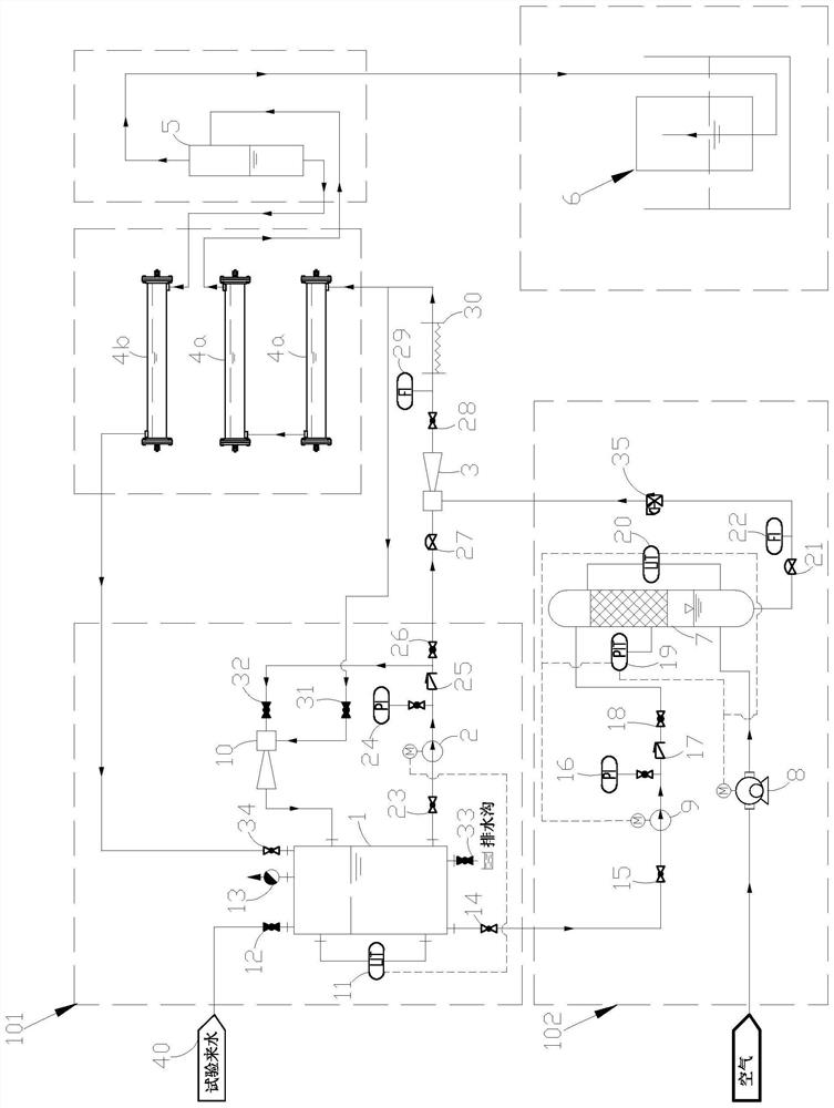
The invention provides a test system for simulating intermediate hydrogen removal separation effect in electrolytic chlorine production. The test system comprises a circulating water supply system, a pressurizing and air dissolving system, a first electrolytic chlorine production device, an intermediate hydrogen removal device and a drainage gas collection device, and the circulating water supply system comprises a circulating water inlet pipeline, a circulating water tank, a circulating water pump and a first ejector; and the pressurizing and air dissolving system comprises an air compressor, an air dissolving tank and a pressurizing pump. According to the test system for simulating the intermediate hydrogen removal separation effect in the electrolytic chlorine production process, seawater in the circulating water tank is pressurized and pumped into the dissolved air tank by using the pressurizing pump, and air is conveyed into the dissolved air tank by using the air compressor, so that the air is dissolved in water to form dissolved air water, the process of generating hydrogen during electrolytic chlorine production and the air-liquid mixed flow state of an electrolytic solution are simulated, and the air-liquid separation effect of the intermediate hydrogen removal device is conveniently verified.

Description

technical field [0001] The invention relates to the technical field of gas-liquid separation, in particular to a test system for simulating the effect of hydrogen removal and separation in the middle of electrolytic chlorine production. Background technique [0002] Sodium hypochlorite sterilization technology is widely used in the disinfection treatment of circulating cooling water in coastal power plants and ship ballast water. At present, the method of electrolyzing seawater or brine to obtain sodium hypochlorite solution is mostly used for on-site preparation. During the electrolysis process, hydrogen gas will be generated, and hydrogen gas is a by-product of the electrolytic chlorine production process. On the one hand, it is flammable and explosive. The gas needs to be quickly discharged out of the electrolytic chlorine production device; on the other hand, for large-scale electrolytic chlorine production equipment, with the progress of the electrolysis process, the ac...

Claims


Application Information

Patent Timeline
IPC IPC(8): G01N33/00G01N1/34
CPCG01N33/0004G01N1/34Y02E60/36
Inventor 王西法卢晓伟郭宇
Owner SUNRUI MARINE ENVIRONMENT ENG
Learn More