Supercharge Your Innovation With Domain-Expert AI Agents!

Time-delay power-off protection circuit

A technology for protecting circuits and capacitors, applied in battery circuit devices, circuit devices, current collectors, etc., can solve the problems of unstable discharge, power grid impact, high requirements, etc., to achieve low power interference, low failure rate, and high reliability. Effect

Pending Publication Date: 2021-04-09
SHENYANG AIRCRAFT DESIGN INST AVIATION IND CORP OF CHINA
View PDF2 Cites 0 Cited by
  • Summary
  • Abstract
  • Description
  • Claims
  • Application Information

AI Technical Summary

Problems solved by technology

[0002] There are two common power supply output circuits: one is that the power supply directly supplies power to the load after filtering. When the power supply is powered off, the load terminal immediately loses power. , the load side cannot work normally; secondly, after the power supply is filtered, a large capacitor is connected in parallel to supply power to the load. The power grid has a certain impact

Method used


Image

  • Time-delay power-off protection circuit
  • Time-delay power-off protection circuit

Examples


Embodiment Construction

[0017] In order to make the purpose, technical solution and advantages of the application more clear, the technical solution in the embodiment of the application will be described in more detail below in conjunction with the drawings in the embodiment of the application.

[0018] In order to overcome the technical problems existing in traditional power supplies, this application provides a delayed power-off protection circuit to achieve the purpose of small start-up inrush current, anti-reverse connection of power supply, and delayed power-off.

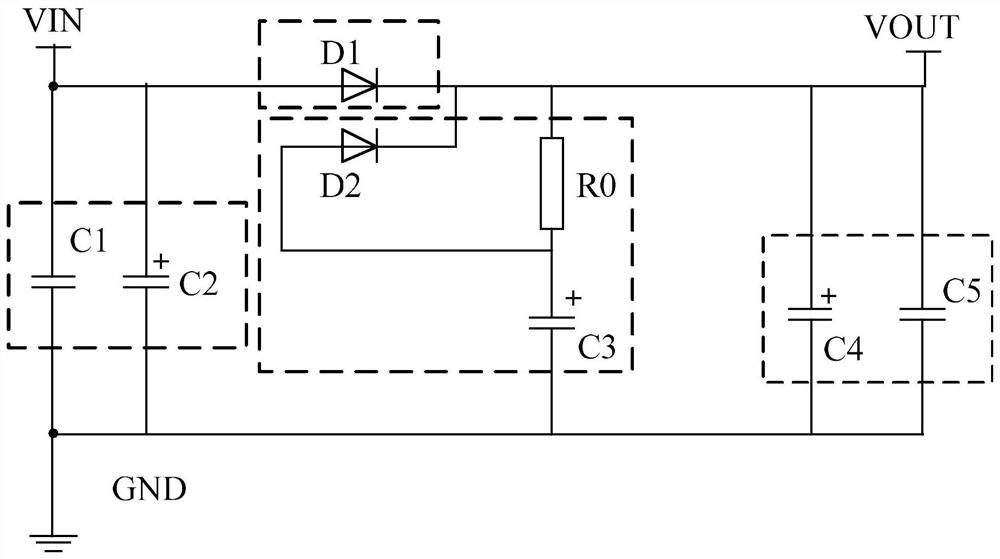
[0019] Such as figure 1 As shown, the delayed power-off protection circuit of this application mainly includes a charging filter circuit, an anti-reverse connection circuit, a charging and discharging circuit, and a discharging filtering circuit. The charging and filtering circuit is composed of a capacitor C1 and a capacitor C2. The capacitor C1 and capacitor C2 are connected to the ground, which is mainly used to filter out the high...


PUM


Abstract

The invention provides a time-delay power-off protection circuit. The protection circuit comprises: a charging filter circuit composed of a capacitor C1 and a capacitor C2, wherein a power supply is grounded through the capacitor C1 and the capacitor C2 which are connected in parallel after being input, and is used for filtering high-frequency and low-frequency signal interference brought by the input power supply; and an anti-reverse-connection circuit composed of a diode D1, wherein a voltage input power supply is connected with the anode of the diode D1 after being input, the cathode of the diode D1 is connected to power supply output, and damage caused by reverse connection of the anode and the cathode of the input power supply is prevented; a charging and discharging circuit formed by a current-limiting resistor R0, a charging and discharging capacitor C3 and a diode D2, wherein the positive end of the current-limiting resistor R0 is connected with the cathode of the diode D1, one path of the negative end of the current-limiting resistor R0 is connected with the charging and discharging capacitor C3, the other path of the negative end of the current-limiting resistor R0 is connected with the anode of the diode D2, and the cathode of the diode D2 is connected with the cathode of the diode D1 and then is connected with power supply output for realizing charging and discharging management of the charging-discharging capacitor C3; and a discharging filtering circuit formed by a capacitor C4 and a capacitor C5, wherein one end of the capacitor C4 and one end of the capacitor C5 which are connected in parallel are connected with power output, and the other end of the capacitor C4 and the other end of the capacitor C5 are grounded.

Description

technical field [0001] The application belongs to the technical field of aircraft power management, and in particular relates to a delayed power-off protection circuit. Background technique [0002] There are two common power supply output circuits: one is that the power supply directly supplies power to the load after filtering. When the power supply is powered off, the load terminal immediately loses power. , the load side cannot work normally; secondly, after the power supply is filtered, a large capacitor is connected in parallel to supply power to the load. The power grid has a certain impact. Contents of the invention [0003] The purpose of the present application is to provide a delayed power-off protection circuit to solve or alleviate at least one problem in the background technology. [0004] The technical solution of the present application is: a delayed power-off protection circuit, the circuit comprising: [0005] The charging and filtering circuit compose...

Claims


Application Information

Patent Timeline
Patent Type & Authority Applications(China)
IPC IPC(8): H02P27/08H02J7/34H02M1/32
CPCH02P27/08H02J7/345H02M1/32H02J2207/50
Inventor 张庆超刘亚兵李征鸿
Owner SHENYANG AIRCRAFT DESIGN INST AVIATION IND CORP OF CHINA
Features
  • R&D
  • Intellectual Property
  • Life Sciences
  • Materials
  • Tech Scout
  • Unparalleled Data Quality
  • Higher Quality Content
  • 60% Fewer Hallucinations
Learn More