Mask for deposition and method for manufacturing same

An evaporation and masking technology, which can be used in semiconductor/solid-state device manufacturing, organic light-emitting device manufacturing/processing, electrical components, etc., and can solve the problems of reducing the evaporation efficiency and evaporation quality of evaporation masks.

Pending Publication Date: 2021-04-09
LG INNOTEK CO LTD
View PDF7 Cites 0 Cited by
  • Summary
  • Abstract
  • Description
  • Claims
  • Application Information

AI Technical Summary

Problems solved by technology

[0009] A plurality of the grooves can be formed by an etching process such as etching, wherein, when forming a plurality of the grooves, stress caused by etching may occur, and due to this stress, the evaporation mask is bent, thereby reducing the utilization of the evaporation mask. Mask deposition efficiency and deposition quality

Method used


Image

  • Mask for deposition and method for manufacturing same
  • Mask for deposition and method for manufacturing same
  • Mask for deposition and method for manufacturing same

Examples


preparation example Construction

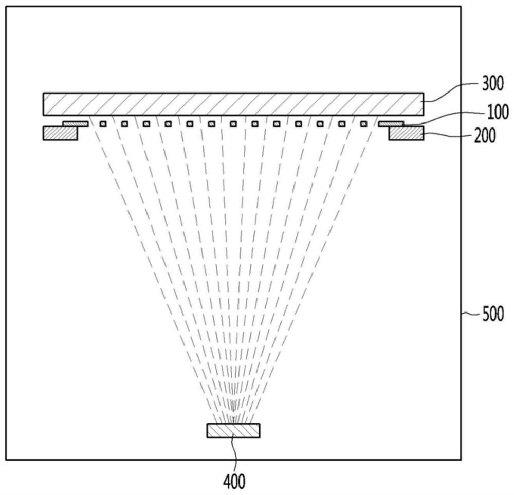
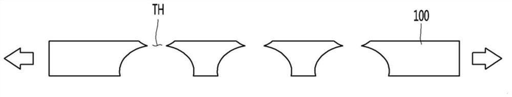
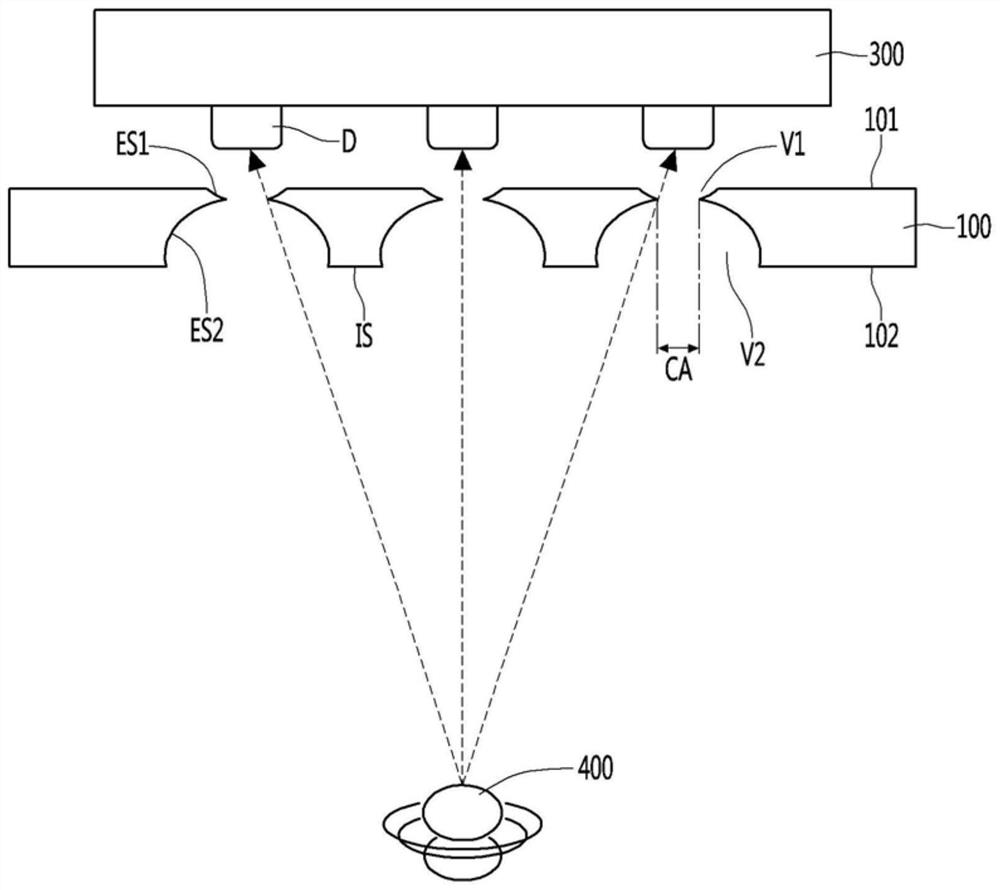
[0214] The method for preparing a mask for evaporation of a metal material used for OLED pixel evaporation can prepare the mask for evaporation of the embodiment, which includes the following steps: the first step is to prepare a base metal plate with a thickness of 20 μm to 30 μm; In the second step, a patterned photoresist layer is arranged on one surface of the base metal plate, and the opening of the photoresist layer is half-etched, thereby forming a pattern on one surface of the base metal plate. Grooves are formed on the base metal plate, and a patterned photoresist layer is arranged on the other surface of the base metal plate opposite to the one surface, and the opening of the photoresist layer is etched, thereby forming a through-holes connected by grooves on one surface of the base metal plate; and a third step of removing the photoresist layer, thereby forming a mask for evaporation including forming holes formed in the through-holes. A large surface hole on the on...

Embodiment 1

[0248] Small surface holes and large surface holes are formed in the effective part, and a plurality of dot-shaped first grooves are formed in the non-effective part. After preparing a mask for evaporation, after forming a plurality of second grooves in the non-evaporation part , Measure the TP (total pitch, total pitch) difference and straightness of the mask for evaporation.

[0249] Wherein, the area of ​​the plurality of first grooves accounts for 45% of the total area of ​​the non-effective portion.

[0250] In addition, the TP (total pitch, total pitch) difference is the difference between the lengths of the upper surface and the lower surface measured based on the direction in which the deposition mask is stretched, and the straightness is that the unbent When the position of the vapor deposition mask is assumed to be 0, the measured difference between the highest point of the upper and lower parts of the bend and 0.

Embodiment 2

[0252] Except that the shape of the first groove is striped, after preparing the mask for evaporation by the same method as in Example 1, after forming a plurality of second grooves in the non-evaporation part, measure the TP (total) of the mask for evaporation. pitch, total pitch) difference and straightness.


PUM

PropertyMeasurementUnit
diameteraaaaaaaaaa
diameteraaaaaaaaaa
diameteraaaaaaaaaa

Abstract

A mask for deposition according to an embodiment includes a deposition region for forming a deposition pattern, and a non-deposition region in addition to the deposition region. The deposition region includes a plurality of effective portions spaced apart from each other in a longitudinal direction, and non-effective portions in addition to the effective portions. The effective portions include: a plurality of small surface holes formed on one surface thereof, and a plurality of large surface holes formed on the other surface opposite from the one surface; and through-holes for communicating the small surface holes and the large surface holes, and island portions between the plurality of through-holes. The non-effective portions include a plurality of first grooves spaced apart from each other. The first grooves are formed to be disposed apart from each other and constitute 10-60% of the total area of the non-effective portions.

Description

technical field [0001] The embodiment relates to a mask for vapor deposition and a preparation method thereof. Background technique [0002] Display devices are being applied to various devices. For example, display devices are applied not only to small devices such as smartphones and tablet PCs but also to large devices such as televisions, monitors, and public displays. In particular, demand for ultra-high-definition UHD (Ultra High Definition) above 500PPI (Pixel Per Inch: Pixel Per Inch) is increasing recently, and high-definition display devices are being applied to small devices as well as large devices. Therefore, interest in techniques for achieving low power and high definition is also increasing. [0003] Commonly used display devices can be roughly classified into LCD (Liquid Crystal Display: Liquid Crystal Display) and OLED (Organic Light Emitting Diode: Organic Light Emitting Diode), etc. according to the driving method. [0004] As a display device driven by...

Claims


Application Information

Patent Timeline
Patent Type & Authority Applications(China)
IPC IPC(8): H01L51/56H01L51/00
CPCC23F1/02C23F1/04H10K71/164H10K71/166H10K71/00
Inventor 孙晓源严太寅曹守铉
Owner LG INNOTEK CO LTD
Why Eureka
Try Eureka