Bogie
A bogie and frame technology, applied in the field of bogies, can solve the problems of large vibration and large space occupied by the drive device, and achieve the effects of good vibration absorption, good energy absorption and vibration reduction.
- Summary
- Abstract
- Description
- Claims
- Application Information
AI Technical Summary
Problems solved by technology
Method used
Image

Examples
Embodiment 1
[0061] This embodiment provides a bogie. The bogie can be applied to a rail vehicle. The rail vehicle can be a diesel locomotive or an electric locomotive, and can be an EMU, subway, light rail, or tram.
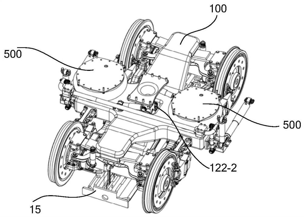
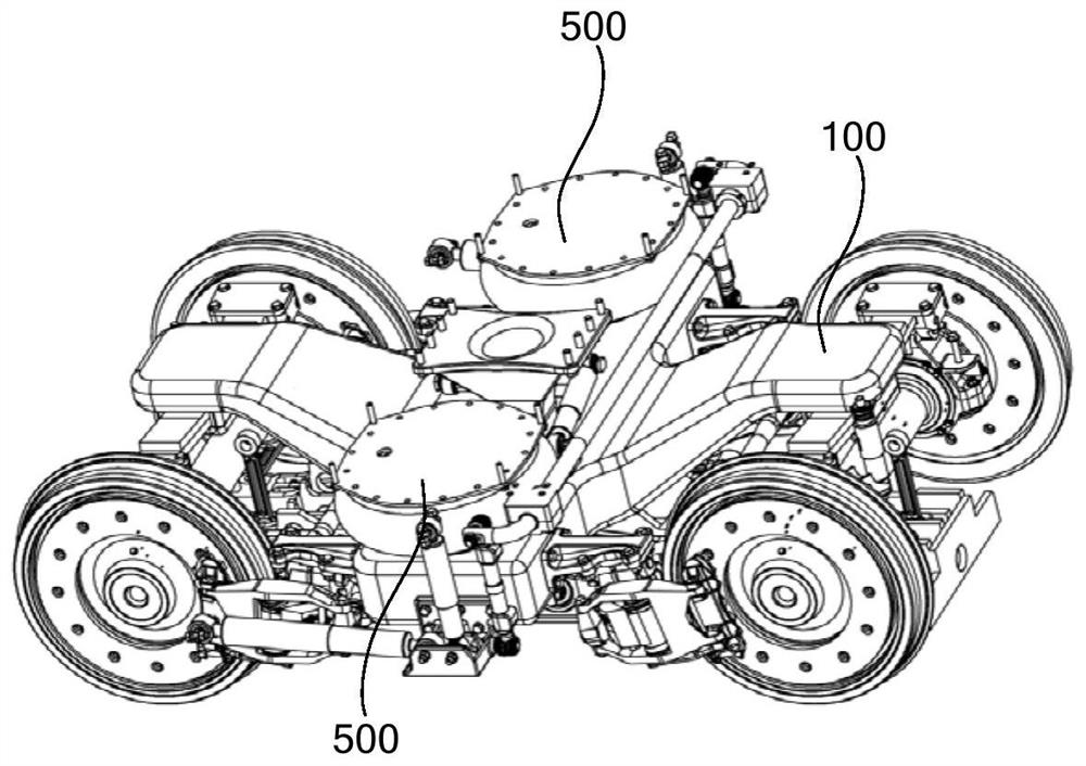
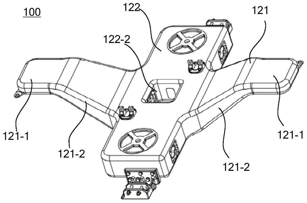
[0062] figure 1 It is a schematic diagram of a bogie according to an embodiment of the present application; figure 2 for figure 1 Another schematic view of the bogie shown; image 3 It is a schematic diagram of the framework of the bogie in the embodiment of the present application; Figure 4 for image 3 Sectional view at the frame beam.
[0063] Such as figure 1 , figure 2 , image 3 and Figure 4 As shown, the bogie of the embodiment of the present application includes a frame 100 and a linear motor 15, and the linear motor 15 is installed on the frame 100; the frame 100 includes:
[0064] rigid frame body 111;
[0065] a layer of composite material 112 fixed at least in the outer surface of the frame body for securing the position of the truck mount, the layer ...
Embodiment 2
[0117] This embodiment provides a bogie, which has some features on the basis of the first embodiment.
[0118] The longitudinal direction mentioned in this embodiment is the direction parallel to the railway line, the transverse direction is the direction perpendicular to the railway line, the vertical direction is the vertical direction, and the longitudinal direction is the extension direction of the railway line, that is, the longitudinal direction is the running direction of the bogie.
[0119] Figure 7 It is a schematic structural diagram of the bogie provided in Embodiment 2 of the present application, Figure 8 for Figure 7 A magnified view of region A in the middle, Figure 9 A top perspective view of the frame in the bogie provided in Embodiment 2 of the present application, Figure 10 The bottom perspective view of the frame in the bogie provided for the second embodiment of the present application.
[0120] Such as Figure 7 to Figure 10 As shown, the bogie...
Embodiment 3
[0141] The embodiment of the present application provides a bogie, which has the following characteristics on the basis of the second embodiment.
[0142] In order to make the linear motor 15 work normally, it is necessary to pre-lay an induction plate capable of generating electromagnetic induction with the linear motor 15 on the track.
[0143] Such as Figure 17 As shown, the linear motor 15 is hoisted and installed at the bottom of the frame 100 , and the axle 311 is located between the frame 100 and the linear motor 15 .
[0144] Such as Figure 16 As shown, along the longitudinal direction, the length of the linear motor 15 is equivalent to the length of the frame 100 , and the length of the linear motor 15 is also greater than the length of the frame 100 .
[0145] In the process of illustrating the bogie of the embodiment of the present application, the Figure 17The part on the left side of the page is defined as the front end of the bogie, and the part on the righ...
PUM
 Abstract
Description
Claims
Application Information