Environment-friendly chemical catalyst storage device
A technology for storage devices and catalysts, applied in packaging, large containers, transportation and packaging, etc., can solve problems affecting production quality, reducing catalytic effects, troubles, etc., to save time for retrieving materials, prevent catalyst leakage, and avoid excessive removal many effects
- Summary
- Abstract
- Description
- Claims
- Application Information
AI Technical Summary
Problems solved by technology
Method used
Image

Examples
Embodiment Construction
[0025] The following will clearly and completely describe the technical solutions in the embodiments of the present invention with reference to the accompanying drawings in the embodiments of the present invention. Obviously, the described embodiments are only some of the embodiments of the present invention, not all of them. Based on the embodiments of the present invention, all other embodiments obtained by persons of ordinary skill in the art without making creative efforts belong to the protection scope of the present invention.
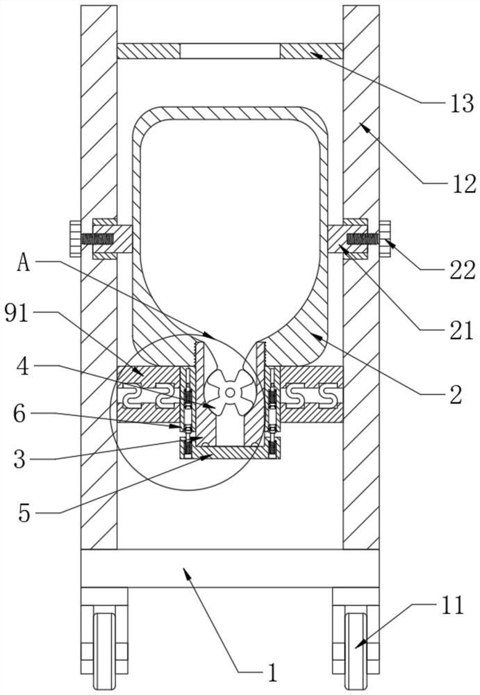
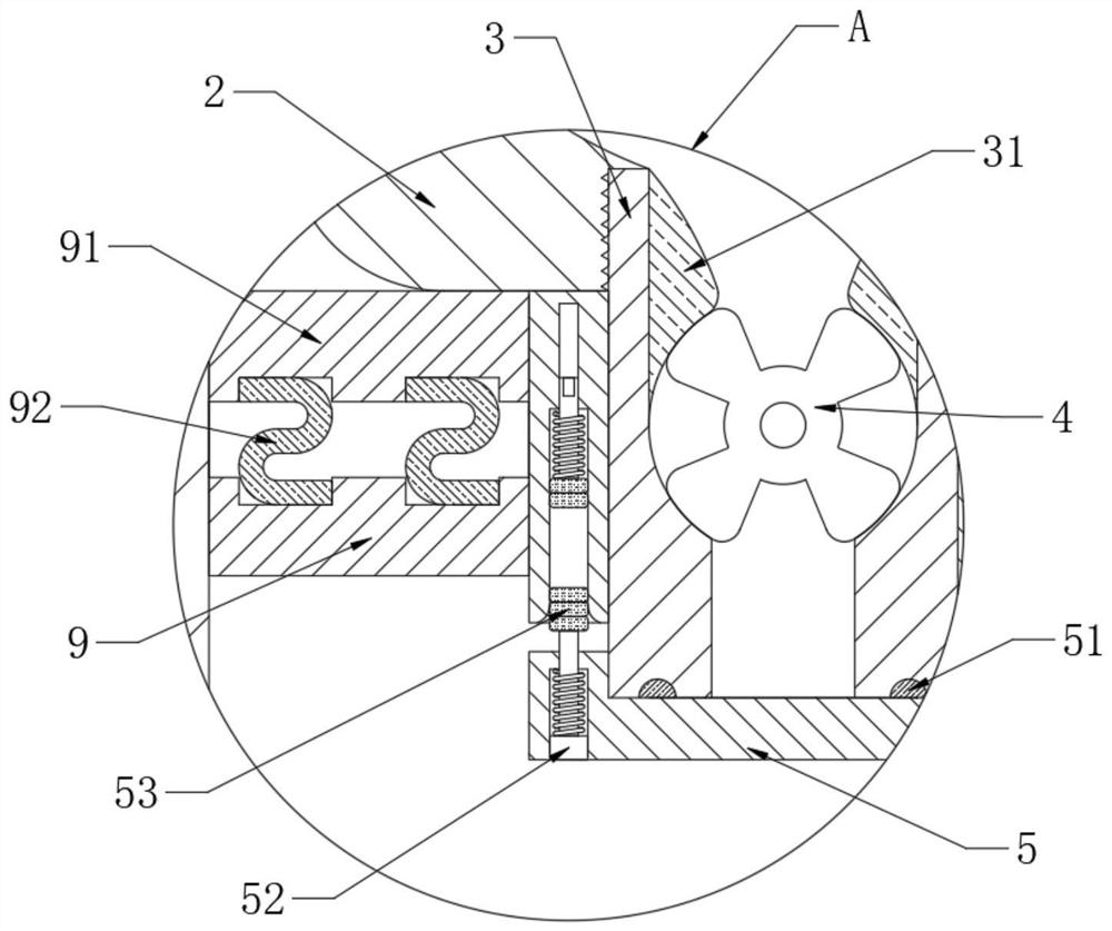
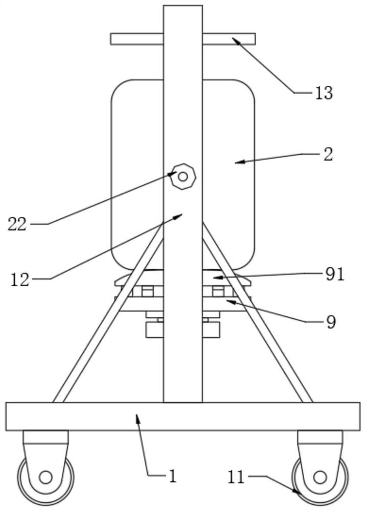
[0026] see Figure 1 to Figure 6 , the present invention provides a technical solution:
[0027] An environment-friendly chemical catalyst storage device, comprising a trolley 1 and a tank body 2. The bottom end of the trolley 1 is connected with four pulleys 11 through brackets, and the upper end of the trolley 1 is welded with support plates 12 symmetrically. Between the two supporting plates 12, a U-shaped clamping plate 13, a tank body 2 and...
PUM
 Abstract
Description
Claims
Application Information
PatSnap Eureka turns technology decisions into work you can execute. Powered by our Innovation Knowledge Graph, it runs expert workflows across engineering, life sciences, materials and intellectual property. Get your review-ready output in minutes.


