Plugging method for dewatering well in foundation pit
A technology for dewatering wells and foundation pits, which is applied in basic structure engineering, construction, etc., and can solve problems such as permanent water seepage of the structural floor, failure to block, incorrect location of dewatering wells, etc.
- Summary
- Abstract
- Description
- Claims
- Application Information
AI Technical Summary
Problems solved by technology
Method used
Image

Examples
Embodiment 1
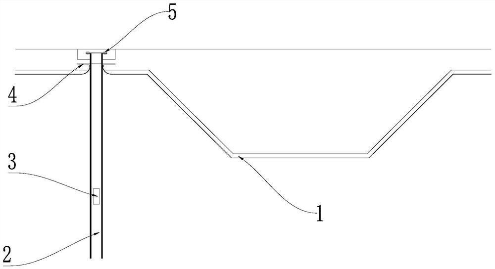
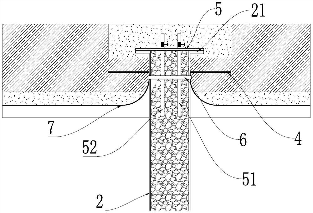
[0027] Example 1: See figure 1 with figure 2 , a method for plugging a dewatering well in a foundation pit according to the present embodiment includes the following steps: S1: select the position of the dewatering well, and insert a steel pipe 2 as the well wall of the dewatering well; S2: weld a water stop ring on the neck of the steel pipe 2 4. Weld the connecting ring 21 on the top of the steel pipe 2; S3: Install the waterproof coiled material 7 on the outer wall of the steel tube 2, and the waterproof coiled material 7 extends from the bottom of the well to the bottom of the water-stop ring 4; S4: Install a water-stop copper strip under the water-stop ring 4 Clamp 6, water-stop copper strip clamp 6 is used to clamp the waterproof membrane 7; S5: Lay the base plate 1 on both sides of the foundation pit and the dewatering well, and the base plate 1 is provided with a reserved sealing position, and the reserved sealing position Install the steel pipe 2 in the middle; S6: ...
Embodiment 2
[0028] Embodiment 2: In step S1 of this embodiment, dewatering wells are selected around the lowest point of the foundation pit, and the water level is lowered to 50 cm below the lowest point of the foundation pit. In the step S1 of this embodiment, excavation is also included. The steel pipe 2 is cut to be 25 cm lower than the top of the bottom plate 1. The steel pipe 2 has a wall thickness of 1-2 cm and a diameter of 30 cm. In step S1 of this embodiment, before the steel pipe 2 is inserted, a plurality of slurry holes are drilled on the bottom side wall of the steel pipe 2 . It can effectively spread the slurry, replacing the traditional method of spreading from the bottom of the precipitation well. In the step S3 of this embodiment, it includes brushing the adhesive on the outer wall of the steel pipe 2, and attaching a rainwater expansion water-stop strip under the water-stop ring 4, and rolling the waterproof coiled material 7 along the outer wall of the dewatering well u...
Embodiment 3
[0029] Embodiment 3: In step S7 of this embodiment, the manhole cover 5 is provided with a first steel pipe hole 51 and a second steel pipe hole 52, the first steel pipe hole 51 is used for grouting, and the second steel pipe hole 52 is used for pressure relief and overflow pulp. Gate valves are added in the first steel pipe hole 51 and the second steel pipe hole 52, which can be closed and opened at any time to control the grouting and unloading water head pressure. In the step S8 of this embodiment, after sealing the well cover 5 and grouting before the water pressure rises, open the second steel pipe hole 52, then open the first steel pipe hole 51, and inject pure cement slurry along the first steel pipe hole 51 , when the second steel pipe hole 52 has grout flowing out, close the second steel pipe hole 52, and carry out the second grouting; the grouting adopts cement water glass double liquid slurry, the ratio is 1:0.5, when the grouting pressure gauge shows that it reache...
PUM
 Abstract
Description
Claims
Application Information
 - R&D
- Intellectual Property
- Life Sciences
- Materials
- Tech Scout
- Unparalleled Data Quality
- Higher Quality Content
- 60% Fewer Hallucinations
Browse by: Latest US Patents, China's latest patents, Technical Efficacy Thesaurus, Application Domain, Technology Topic, Popular Technical Reports.
© 2025 PatSnap. All rights reserved.Legal|Privacy policy|Modern Slavery Act Transparency Statement|Sitemap|About US| Contact US: help@patsnap.com