Tightly-arranged engine tail gas treatment system

An exhaust gas treatment and engine technology, applied in engine components, combustion engines, machines/engines, etc., can solve the problems of low treatment efficiency, difficult to install after-treatment systems, poor stability, etc., so as to improve catalytic efficiency, facilitate full utilization, Guaranteed effect at high temperature

Active Publication Date: 2021-04-13
DONGFENG AUTOMOBILE COMPANY
View PDF6 Cites 2 Cited by
  • Summary
  • Abstract
  • Description
  • Claims
  • Application Information

AI Technical Summary

Problems solved by technology

[0004] The purpose of the present invention is to overcome the problems of difficult installation, poor stability, and low processing efficiency of the existing post-processing systems that meet the National VI standards in the prior art, and provide a compact structure, good stability, and high processing efficiency. Tight arrangement after treatment assembly

Method used


Image

  • Tightly-arranged engine tail gas treatment system
  • Tightly-arranged engine tail gas treatment system
  • Tightly-arranged engine tail gas treatment system

Examples


Embodiment 1

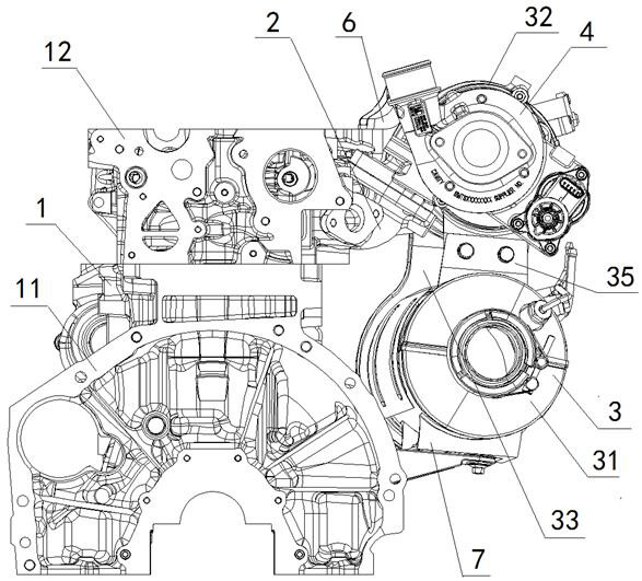
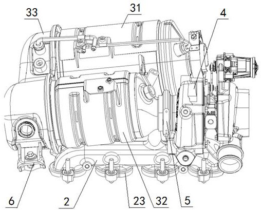
[0068] The exhaust manifold 2, the aftertreatment assembly 3 and the supercharger 4 are all fixedly arranged on one side of the engine 1; the aftertreatment assembly 3 includes a selective catalytic reduction particulate matter trap 31, an oxidation catalyst 32 And the mixer assembly 33, the selective catalytic reduction particulate matter trap 31 is located below the oxidation catalyst 32, the rear end of the selective catalytic reduction particulate matter trap 31 passes through the mixer assembly 33 and the oxidation catalytic converter The rear end of 32 is connected, and the selective catalytic reduction particulate matter trap 31, oxidation catalyst 32 and mixer assembly 33 are arranged in a U shape; the exhaust manifold 2 is arranged between the engine 1 and the oxidation catalyst 32 , the front of the exhaust manifold 2 communicates with the front end of the oxidation catalyst 32 through the supercharger 4, and the exhaust manifold 2 and the particulate matter trap 31 f...

Embodiment 2

[0070] Embodiment 2 is basically the same as Embodiment 1, and its difference is:

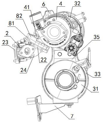
[0071]The engine 1 includes a cylinder block 11 and a cylinder head 12 fixedly arranged on the top of the cylinder block 11, the top of the mixer assembly 33 is connected with the cylinder head 12 through the upper fixing bracket 6, and the bottom of the oxidation catalyst 32 is The side of the cylinder block 11 is connected through the lower fixing bracket 7; one side of the exhaust manifold 2 has a plurality of manifold inlets 21 corresponding to the engine exhaust ports, and the manifold inlets 21 is sealed with the engine exhaust port on the side of the cylinder head 12, the manifold inlet 21 is provided with a manifold mounting flange 23, and the exhaust manifold 2 is fixed on the cylinder head 12 through the manifold mounting flange 23; The front end of the oxidation catalyst 32 is fixedly provided with an after-treatment assembly inlet flange 34; the turbine outlet end of the supercharge...

Embodiment 3

[0073] Embodiment 3 is basically the same as Embodiment 2, and its difference is:

[0074] The outer walls of the supercharger 4 and the exhaust manifold 2 are covered with a heat insulating layer;

[0075] The bottom of the front end of the oxidation catalyst 32 is connected as a whole with the top of the front end of the selective catalytic reduction particulate matter trap 31 through an auxiliary bracket 35 , and a hot air stagnation area 36 is formed between the auxiliary bracket 35 and the mixer assembly 33 The rear end of the selective catalytic reduction particulate matter trap 31 communicates with the rear end of the oxidation catalyst 32 through the mixer assembly 33, and the front end of the selective catalytic reduction particulate matter trap 31 is sealed with the vehicle exhaust tailpipe Connect; the supercharger 4 includes a compressor part and a turbine part, the front end of the turbine part is fixedly connected with the rear end of the compressor part, the rea...


PUM


Abstract

A tightly-arranged engine tail gas treatment system comprises an exhaust manifold, a post-treatment assembly and a supercharger which are fixedly arranged on one side of an engine, wherein the post-treatment assembly comprises a particulate matter catcher for selective catalytic reduction, an oxidation catalytic converter and a mixer assembly; the rear end of the particulate matter catcher for selective catalytic reduction is communicated with the rear end of the oxidation catalytic converter through the mixer assembly, and the particulate matter catcher for selective catalytic reduction, the oxidation catalytic converter and the mixer assembly are arranged in a U shape; the exhaust manifold is arranged between the engine and the oxidation catalytic converter, the front portion of the exhaust manifold is communicated with the front end of the oxidation catalytic converter through the supercharger, and the exhaust manifold, the supercharger and the particulate matter catcher 31 for selective catalytic reduction are arranged in a U shape; and the side part of the exhaust manifold is communicated with an engine exhaust port in the side part of the engine. The design is compact in arrangement, a waste gas flowing path is short, the waste gas heat loss is small, the conversion efficiency of catalysts is high, and strict emission standards are met.

Description

technical field [0001] The invention relates to an engine post-treatment structure, in particular to a close-arranged engine exhaust treatment system, which is particularly suitable for the treatment of engine exhaust. Background technique [0002] The engine aftertreatment assembly is an integrated multifunctional assembly structure. When the engine is working, the post-treatment plays the role of diverting the exhaust gas, collecting energy for reuse, treating particulate matter in the exhaust gas, treating pollutants in the exhaust gas, and making the exhaust gas meet the emission requirements. [0003] At present, with the upgrading of national emission regulations and the implementation of the national sixth-stage motor vehicle pollutant emission standards, the engine puts forward stricter restrictions on after-treatment emissions. Existing vehicles that meet the national sixth-stage motor vehicle pollutant emission standards The post-processing system of the diesel en...

Claims


Application Information

Patent Timeline
Patent Type & Authority Applications(China)
IPC IPC(8): F01N3/035F01N3/10F01N13/10F01N13/18F01N3/20F01N3/28F02B37/00
CPCF01N3/035F01N3/106F01N13/10F01N13/102F01N13/1805F01N3/2066F01N3/2892F02B37/00Y02T10/12
Inventor 陈震毛勇余国强邓基峰江琳琳刘凯程庆姚强殷勇刘蓉赵昌鹏潘师民王亚强
Owner DONGFENG AUTOMOBILE COMPANY
Why Eureka
Try Eureka