Optical imaging system, module and electronic equipment

An optical imaging system and imaging surface technology, applied in optics, optical components, instruments, etc., can solve the problems of small light transmission and small field of view, and achieve the effects of high practicability, expanded field of view, and strong practicability

Pending Publication Date: 2021-04-13
JIANGXI JINGCHAO OPTICAL CO LTD
View PDF0 Cites 2 Cited by
  • Summary
  • Abstract
  • Description
  • Claims
  • Application Information

AI Technical Summary

Problems solved by technology

However, because the periscope camera lens has a smaller amount of light than ordinary lenses and a smaller field of view, it has become a technical difficulty that needs to be overcome.

Method used


Image

  • Optical imaging system, module and electronic equipment
  • Optical imaging system, module and electronic equipment
  • Optical imaging system, module and electronic equipment

Examples


Embodiment 1

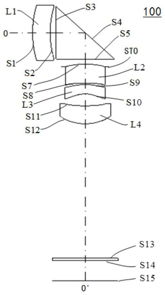
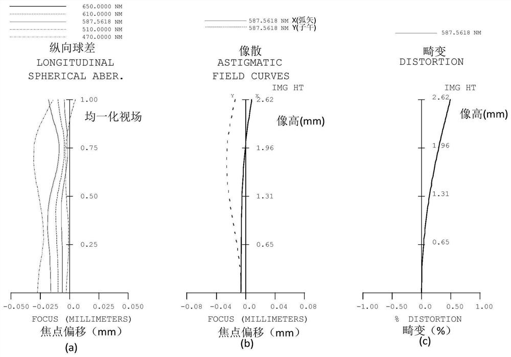
[0069] see Figure 1-Figure 2 As shown, the optical imaging system 100 of this embodiment satisfies the conditions of Table 1 and Table 2 below.

[0070] Table 1

[0071]

[0072]

[0073] Wherein, EFL is the effective focal length of the optical imaging system 100, FNO is the aperture number of the optical imaging system 100, TTL21 is the distance from the object side of the first lens L1 to the reflective surface of the prism on the optical axis OO', and TTL22 is the center of the reflective surface of the prism The distance to the imaging surface S15 on the optical axis OO', ETL3 is the edge thickness of the effective aperture of the third lens L3, CTL3 is the thickness of the third lens L3 on the optical axis OO', RAD (AngleS1) is the maximum field of view point The radian value of the incident angle of the chief ray passing through the object side of the first lens L1, RAD(FOV) is the radian value of the maximum field of view angle of the optical imaging system 100, ...

Embodiment 2

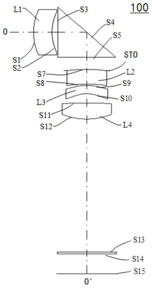
[0088] see Figure 3-Figure 4 As shown, the optical imaging system 100 of this embodiment satisfies the conditions in Table 3 and Table 4 below.

[0089] table 3

[0090]

[0091] Wherein, EFL is the effective focal length of the optical imaging system 100, FNO is the aperture number of the optical imaging system 100, TTL21 is the distance from the object side of the first lens L1 to the reflective surface of the prism on the optical axis OO', and TTL22 is the center of the reflective surface of the prism The distance to the imaging surface S15 on the optical axis OO', ETL3 is the edge thickness of the effective aperture of the third lens L3, CTL3 is the thickness of the third lens L3 on the optical axis OO', RAD (AngleS1) is the maximum field of view point The radian value of the incident angle of the chief ray passing through the object side of the first lens L1, RAD(FOV) is the radian value of the maximum field of view angle of the optical imaging system 100, F1 is the ...

Embodiment 3

[0103] see Figure 5-Figure 6 As shown, the optical imaging system 100 of this embodiment satisfies the conditions in Table 5 and Table 6 below.

[0104] table 5

[0105]

[0106] Wherein, EFL is the effective focal length of the optical imaging system 100, FNO is the aperture number of the optical imaging system 100, TTL21 is the distance from the object side of the first lens L1 to the reflective surface of the prism on the optical axis OO', and TTL22 is the center of the reflective surface of the prism The distance to the imaging surface S15 on the optical axis OO', ETL3 is the edge thickness of the effective aperture of the third lens L3, CTL3 is the thickness of the third lens L3 on the optical axis OO', RAD (AngleS1) is the maximum field of view point The radian value of the incident angle of the chief ray passing through the object side of the first lens L1, RAD(FOV) is the radian value of the maximum field of view angle of the optical imaging system 100, F1 is the ...


PUM


Abstract

The invention discloses an optical imaging system, a module and electronic equipment. The optical imaging system includes, in order from an object side to an image side along an optical axis, a first lens, a prism, a second lens, a third lens and a fourth lens; the first lens has negative refractive power; the object-side surface of the first lens is convex at a position close to the optical axis, and the image-side surface of the first lens is concave at a position close to the optical axis; the prism turns an optical path; the prism is provided with a reflecting surface; the second lens has refractive power; the object side surface of the second lens is a convex surface at a position close to the optical axis; the third lens has refractive power, the object side surface of the third lens is a convex surface at a position close to the optical axis; and the fourth lens has refractive power. The optical imaging system meets the following conditional expressions: 0.1 mm <-1><EFL/(TTL21*TTL22)<0.3 mm <-1>. According to the optical imaging system provided by the embodiment of the invention, the light flux is large while the micro design is met, the view field range is large, and the requirements of high-definition images and long-range shooting are met.

Description

technical field [0001] The invention relates to the technical field of imaging technology, in particular to an optical imaging system, a module and electronic equipment. Background technique [0002] With the miniaturization and ultra-thin design of mobile phones, drones, and tablet computers being favored by consumers, the accessories of electronic products are also further compressed to meet the end products, so that the overall volume of optical lenses is compressed and various miniaturized lenses appear. Design products, but if you want to achieve higher-quality camera functions, the excessive compression of the lens volume will sacrifice the imaging quality, so the periscope camera lens has emerged as the times require, without changing the ultra-thin and miniaturized end products without compressing the lens Volume, the possibility of achieving high-definition image shooting effects. [0003] At present, all kinds of periscope lenses occupy a dominant position in high...

Claims


Application Information

Patent Timeline
Patent Type & Authority Applications(China)
IPC IPC(8): G02B13/00G02B13/18
CPCG02B13/0015G02B13/004G02B13/0065
Inventor 张文燕杨健李明
Owner JIANGXI JINGCHAO OPTICAL CO LTD
Why Eureka
Try Eureka