Inductor component

A technology for inductors and components, applied in the field of inductor components, can solve problems such as reduction in adhesion, and achieve the effect of suppressing the reduction in adhesion

Active Publication Date: 2021-04-13
MURATA MFG CO LTD
View PDF16 Cites 0 Cited by
  • Summary
  • Abstract
  • Description
  • Claims
  • Application Information

AI Technical Summary

Problems solved by technology

The inventors of the present application have found that, for an insulating layer made of such an organic resin, the adhesiveness with the main surface of the magnetic layer may decrease.

Method used


Image

  • Inductor component
  • Inductor component
  • Inductor component

Examples


Embodiment Construction

[0035] One embodiment of the inductor component will be described below. In addition, in the drawings, constituent elements are sometimes shown enlarged for easy understanding. Dimensional ratios of constituent elements may differ from actual ones or from those in other drawings. In addition, hatching is given in cross-sectional views, but hatching of some components may be omitted for easy understanding.

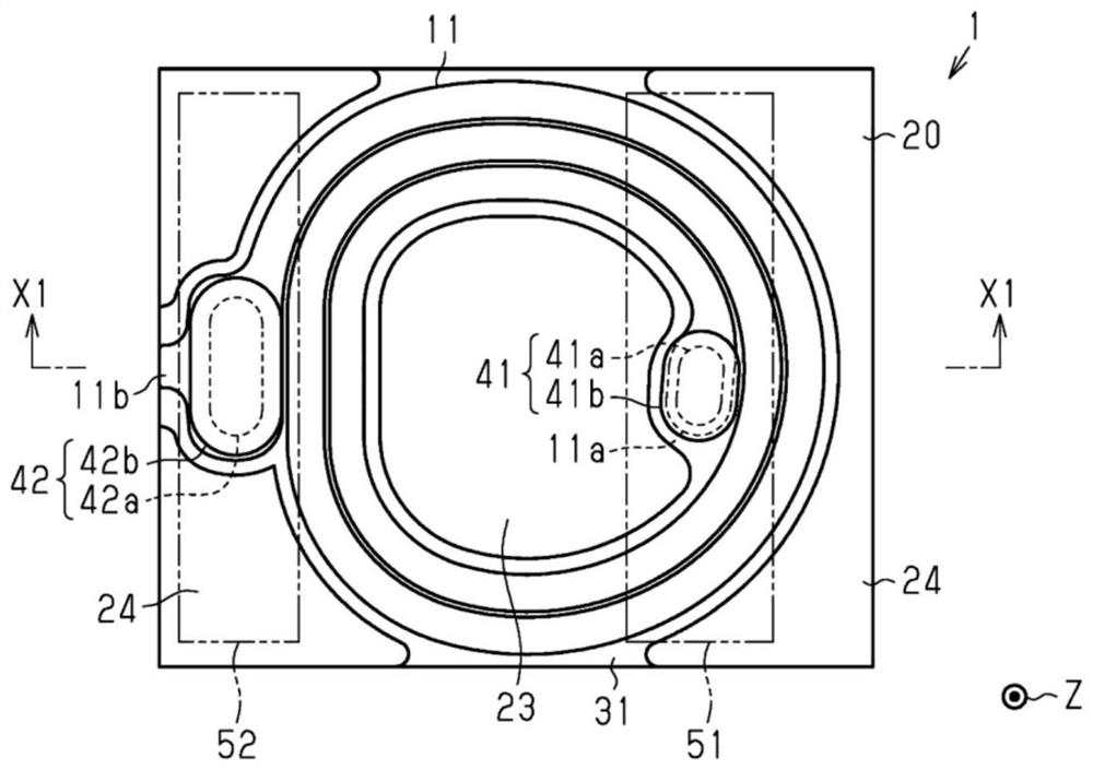
[0036] figure 1 The illustrated inductor component 1 is, for example, a surface-mount inductor component mounted in electronic equipment such as a personal computer, a DVD player, a digital camera, a television, a mobile phone, and an auto control unit. The inductor component 1 is a component that generates impedance in electronic equipment, and has functions such as impedance matching, filtering, resonance, smoothing, rectification, power storage, voltage transformation, distribution, coupling, and conversion.

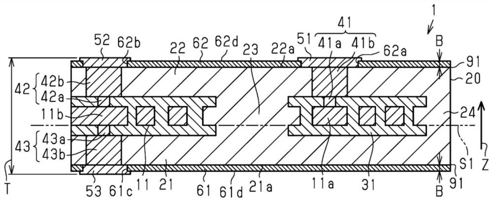
[0037] Such as Figure 1 to Figure 3 As shown, inductor c...


PUM

PropertyMeasurementUnit
thicknessaaaaaaaaaa
thicknessaaaaaaaaaa
thicknessaaaaaaaaaa

Abstract

The invention provides an inductor component in which the adhesiveness between an insulating layer and the principal surface of a magnetic layer is suppressed from deteriorating. The inductor component includes an inductor wiring line that extends in a plane; a magnetic layer (21) that is formed of an organic resin (72) containing a magnetic powder (73) and that covers the inductor wiring line; and a nonmagnetic-body insulating layer (61) that is formed of an organic resin (82) containing an insulating nonmagnetic powder (81) and that covers a principal surface (21a) of the magnetic layer (21). The inductor component further includes a close-contact layer (91) that is located between the magnetic layer (21) and the insulating layer (61) and that contains the magnetic powder (73), the nonmagnetic powder (81), and an organic resin (92).

Description

technical field [0001] The present disclosure relates to inductor components. Background technique [0002] An inductor component to be mounted in an electronic device has, for example, as described in Patent Document 1, an inductor wiring, a pair of magnetic layers made of an organic resin containing magnetic powder and sandwiching the inductor wiring, and a main surface covering the magnetic layer. insulation layer. In Patent Document 1, the insulating layer is formed by treating the main surface of the magnetic layer with phosphate to form an inorganic film. [0003] Patent Document 1: Japanese Patent No. 6024243 [0004] In an inductor component having such a conventional structure, an organic resin such as a solder resist is often used instead of an insulating layer of an inorganic film. The inventors of the present application found that, in an insulating layer made of such an organic resin, the adhesiveness with the main surface of the magnetic layer may be lowered...

Claims


Application Information

Patent Timeline
Patent Type & Authority Applications(China)
IPC IPC(8): H01F17/04H01F27/255
CPCH01F17/04H01F27/255H01F2017/048H01F17/0013H01F2017/0073H01F27/29H01F27/324H01F41/046H01F2027/2809H01F41/041H01F27/2804H01F41/0246
Inventor 山内浩司吉冈由雅工藤谅
Owner MURATA MFG CO LTD
Why Eureka
Try Eureka